The Making of The Rovers


Then

The cardboard prototype was perfect for getting the approximate size of the chassis and position of the steering servos but not good for rigidness.

Original idea was for steering servos to be placed along length of the rover for making it even more rigid. Unfortunately it wasn't the best idea as amount of space on the 'first floor' of the rover wouldn't be used in the most optimal way. Type (and size of the battery) dictated that long and narrow space was needed and servos on the side would have used it all. On the other hand, placing the servos perpendicular left enough space for battery to be placed on its side, on the side of the rover next to the hole for the camera. Length of the battery and size of the servos defined our rover's footprint: 160mm x 110mm.chassis.jpg
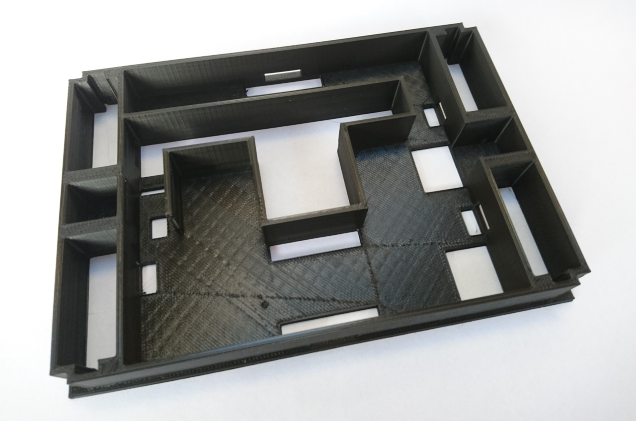
A few prints of the main chassis and we've settled down to exact measures, the position of the Raspberry Pi on the top of it and gap needed for camera to operate under the rover and over.

Read more…

Distraction


Three weeks to go and so many things to do... and yet, making mistakes like getting a PS2 controller instead of a PS3 (USB) version just a few days before the Raspberry Pi Zero W has out turned out to be unforgivable. Unforgivable at least time wise.

Those two (the PS2/3 controller and the PiZero W) are just perfect pair, especially if accompanied with a 128x64 i2c OLED and Adafruit's power boost. They all begged to be put together just a week or so. We had a small misjudgement of how long it was going to take and a couple of hours (or more) ended up being the whole weekend. But here it is:complete-1.jpg

Read more…

Driving


Then

To drive our rover, we created a program that used mqtt messages to send servo signals. Pygame "game" (an application) with key controls was used to send the messages, and move the right wheels in the right places using methods that look like this:
def slantWheels():
    wheelDeg("fl", 60.0)
    wheelDeg("fr", -60.0)
    wheelDeg("bl", -60.0)
    wheelDeg("br", 60.0)
In the mean time we had introduced wheels service. Service that will control appropriate servos depending on which angle we want each wheel to be at and at which speed we would like to drive the wheel at.

Read more…

Software Part 2


Then

It was time to add some Python to the picture. Python is language of choice for the Games Creators Club where we use pygame to make some 2D games (see here for some of the games made in previous years), so it makes perfect sense for it to be the main language for controlling our robot rover.

The method for moving a servo for our rover is quite simple given that most of the work is done in servoblaster (seer Software Part 1):

def moveServo(servoid, angle):
    f = open("/dev/servoblaster", 'w')
    f.write(str(servoid) + "=" + str(angle) + "\n")
    f.close()
A simple scp of the python file to the Raspberry Pi and running it has shown that it is quite quick (especially given it is Raspberry Pi 3).

Read more…

Software Part 1


Then

When all servos and motor controllers (that are to be commended as servos) were wired, we needed a way to control them in the software. Luckily, Raspberry Pi has brilliant piece of software called 'servoblaster' (open source project on the github) which utilizes internal DMA timers for generating precise PWM they way the servos need. Also, it pretends to be a device by creating a pipe file called /dev/servoblaster which acts as simple interface with the 'outside' world. All that is needed,  is for someone to a send line of text in format "<servo_number>=<position>" and servoblaster will move a particular servo to the position. The servos are numbered 0, 1, 2... and in /etc/init.d/servoblaster file we can define OPTS environment variable with "--p1pins=<comma delimited list of GPIO pins>" to link between ordinary number and GPIO pin. GPIO pin numbers correspond to physical pins which makes it even simpler. The servo position is the width of the signal in tens of microseconds, so, 150 corresponds to 1.5ms (1500 micro seconds) which is mid point of servos.

Read more…

Wiring it together


Then

The main interface between the wheels (as pictured in the previous post) and the Raspberry Pi are GPIOs configured to drive RC standard servos - PWM with duty cycle of 1ms (*) for a full left position and 2ms for a full right position for the 'on' part of the cycle and rest of it filled to 20ms (50 times a second) for the 'off' or '0' part of the cycle. That leaves 1.5ms for the center.

(*) modern servos work with far greater range - easily from 0.6ms to 2.4ms and beyond - turning far more than just 180º.

Read more…

Now and then


There are so many things that happened since our inception meeting that it will take some time to catch up. Thus I decided to dedicate each blog to 'then' and 'now'.

Then

The rover needs wheels. The rover needs motors. The rover needs to steer. For motors we originally went with tiny 150RPM motors (@ 6V hoping to drive them at @ ~ 8V when at full speed). See below paragraph about the math that made us switch to exactly the same size motors but geared at 300RPM. For steering we went with a 9650 sized servo.

So, behold a complete GCC rover wheel:wheel1..jpg
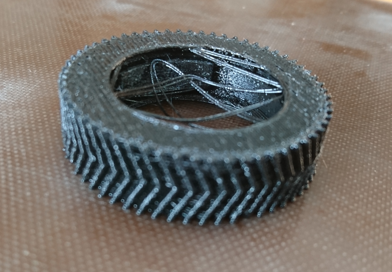
Also, wheels need tyres:

wheel3..jpg

Read more…

How It Began...


[gallery ids="25,24" type="rectangular"]

In October, we began to plan our rover. We discussed how to steer our rover and considered different ways of steering, for example using tank steering or going with standard car steering.

Read more…