Wiring it together
Then
The main interface between the wheels (as pictured in the previous post) and the Raspberry Pi are GPIOs configured to drive RC standard servos - PWM with duty cycle of 1ms (*) for a full left position and 2ms for a full right position for the 'on' part of the cycle and rest of it filled to 20ms (50 times a second) for the 'off' or '0' part of the cycle. That leaves 1.5ms for the center.(*) modern servos work with far greater range - easily from 0.6ms to 2.4ms and beyond - turning far more than just 180º. Each wheel consists of a servo and motor driven by an RC brushless motor controller like this one. Such controllers are usually called ESCs (electronic speed controllers). Since servos are not tiny HXT900 or similar and they all can move at the same time and, on the other hand, motor controllers do provide some BEC (battery eliminating circuit), so the idea was to wire each motor controller's BEC output to one servo - same wheel's servo.
That requires a power source (fancy term for battery) to be distributed in five ways: four motors and the Raspberry Pi itself:
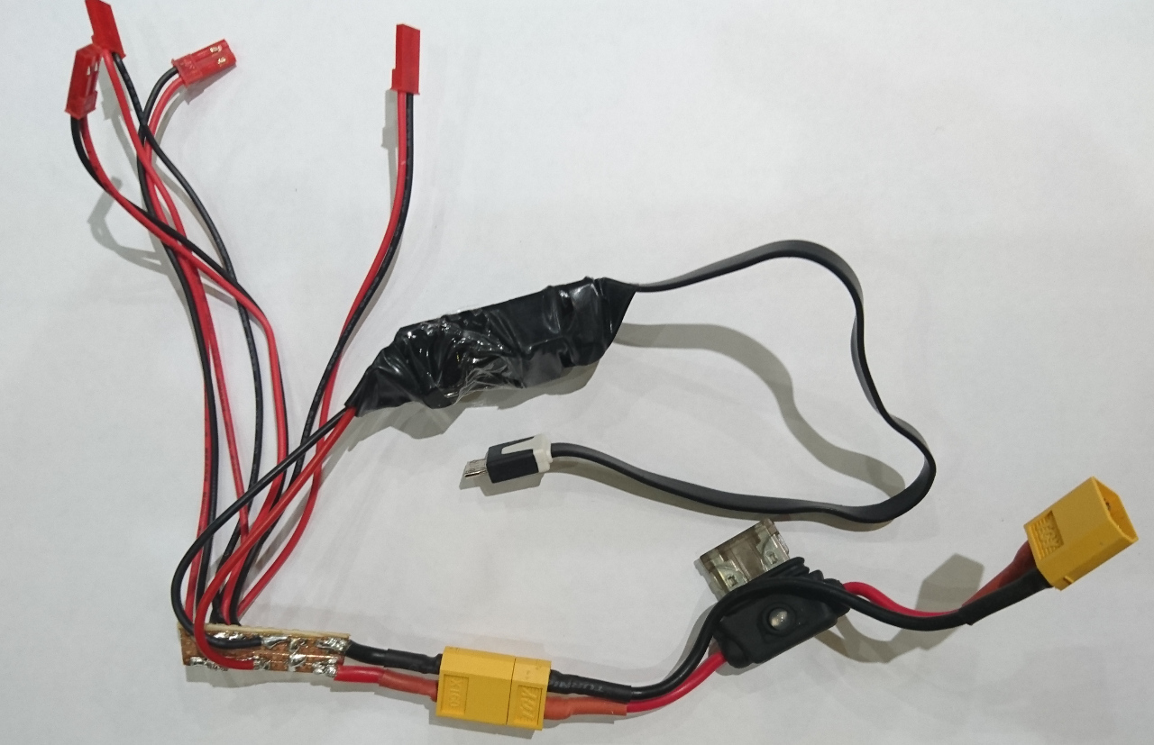
The big black thing above is a DC-to-DC converter (like this one) as battery is going to be more than 5V. At the bottom is a simple 2A fuse which is used used in cars. If we are to use LiPo batteries (and they provide plenty of oomph) that is a sensible precaution as shorting a LiPo battery can result in an explosion! Even ordinary alkaline batteries can heat up and cause plenty of damage if shorted!
All of the above needs to go below the main 'deck' of the rover.
Now
As each motor controller is slightly different in terms of when it starts driving the motor one direction or another. And when it cuts of: it stops driving it when near extreme points. That causes some problems when trying to drive the rover very slowly - especially when trying to rotate on the spot. That causes some wheels not to start moving and not being given any current by motor controller, while other started pushing rover. When all of the wheels turn the rover goes straight (more or less) or rotates on the spot but if there is one wheel that is not driven then it makes much more resistance and the rover goes to the side or rotates around the wheel and not middle point.David has made nice calibration application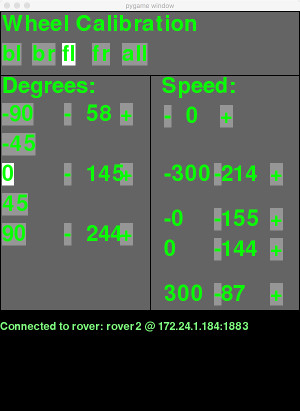 ion in Python, so we can calibrate each wheel's motor controller's 'end points' but even then when talking about fine steps - steps between 'not moving' and 'moving' we have the issue. Also, when end points are set 'on the edge' between working and not working, from time to time motor controller would engage motors even though it shouldn't have making noise when rover is stationary. Daydreaming kicking in... In an ideal world we would have way of measuring current through the motor plus rotary encoders on all axles. Eh...
Comments
Comments powered by Disqus