Distraction
Three weeks to go and so many things to do... and yet, making mistakes like getting a PS2 controller instead of a PS3 (USB) version just a few days before the Raspberry Pi Zero W has out turned out to be unforgivable. Unforgivable at least time wise.
Those two (the PS2/3 controller and the PiZero W) are just perfect pair, especially if accompanied with a 128x64 i2c OLED and Adafruit's power boost. They all begged to be put together just a week or so. We had a small misjudgement of how long it was going to take and a couple of hours (or more) ended up being the whole weekend. But here it is: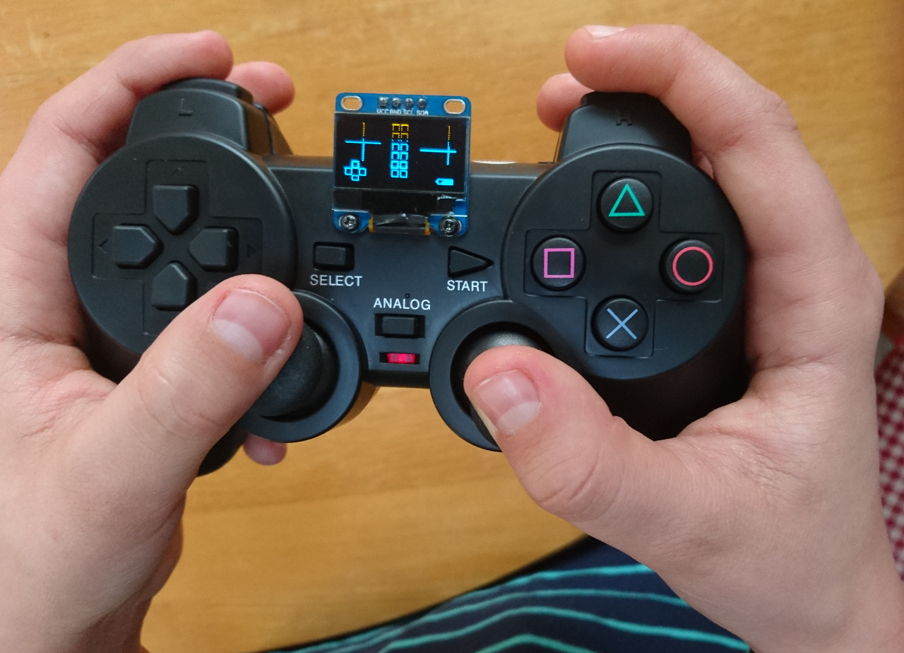 The main component is a PiZero W configured to automatically connect to our WiFi access point (a Raspberry Pi in a green box). It is embedded into the controller itself with a bolted display on top of it so we can can select which rover to control, check if everything is connected and show the state of the battery. Making sure the battery runs too low is really important as Adafruit's power booster is planted so deep inside the controller that its LEDs are not visible from the outside. That was the hardest part.
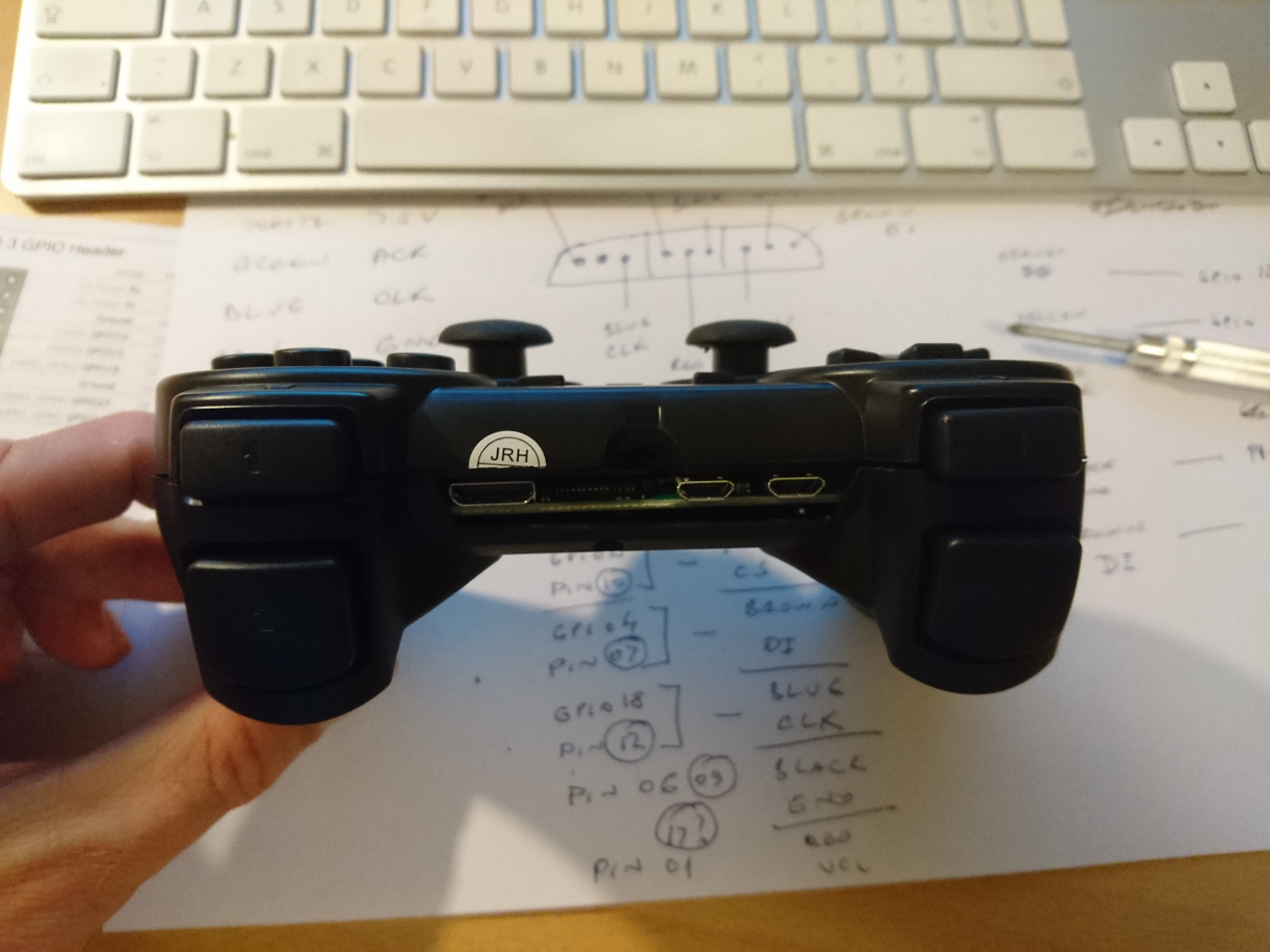
Anyway, lets go through it in the order it was put together: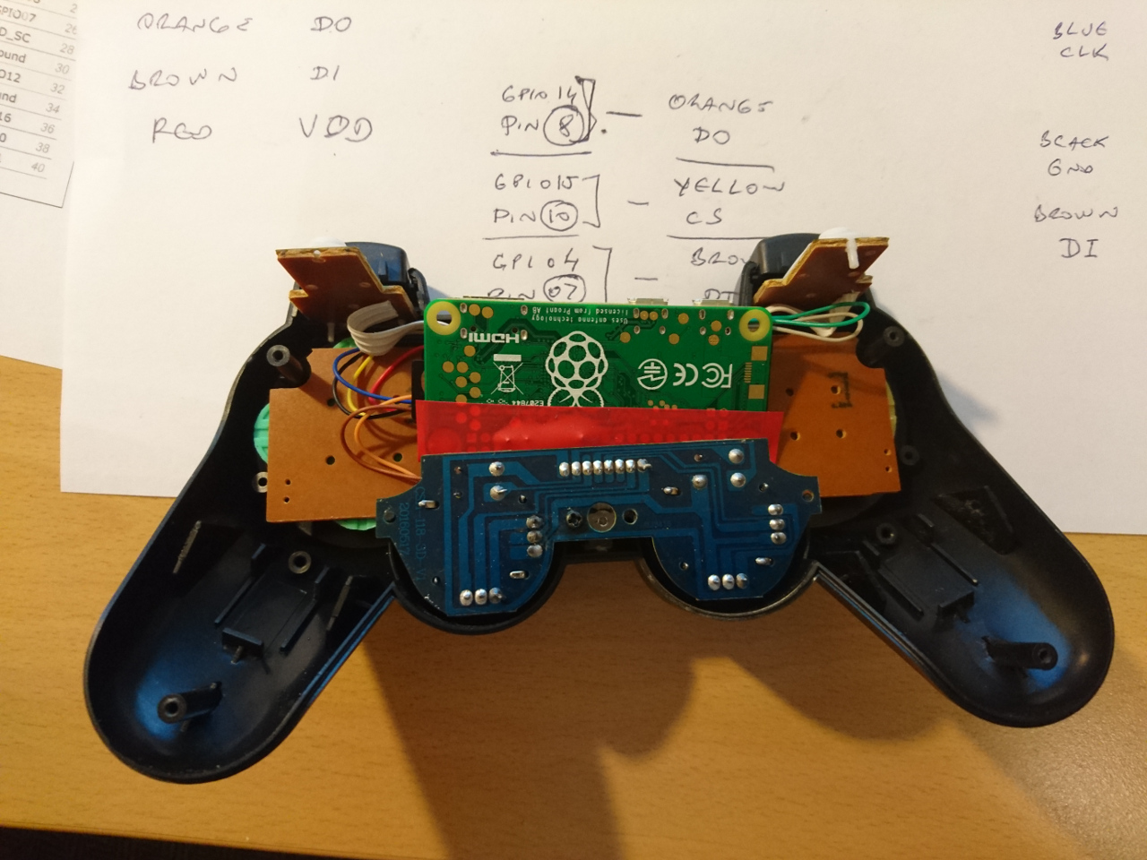 The first question was 'can the PiZero be fitted inside?' - just below the controller's PCB. And even though it is quite a tight fit and it protruding 1mm it at the back it was just the right size. Width wise at least. For the depth - some cables needed to be twisted in and back.
Then, there was the wiring. Luckily there is a kernel driver nicely installed by RetroPie. It is responsible for the reading of the PS2 controller's input (connected to appropriate GPIOs as per driver's documentation). Also, it registers a joystick (/dev/input/js0 for instance) to the system. If this new controller is to be used as PiZero W suggests (wirelessly) then it needs a separate, independent power. An old 850mAh 3S LiPo battery seemed to be the right shape and size to slot into one of the handles of the controller. Actually, that battery itself consisted of 3 separate cells, meaning we had two mistakes, before it was useless (so far only one 'mistake' was used). Such a battery itself is not enough to directly power PiZero as its voltage will vary from 4.2 fully charged to 3.2 discharged. There comes in Adafriut's Power Booster (500mA) which is made exactly for such an application: it steps up a one cell Lithium batteries to 5.2V needed for Raspberry Pi and allows for such, connected, battery to be charged through it. And, the most important part - signals when battery is low so device can be connected to a charger ( a simple USB charger as is used for many phones and similar devices).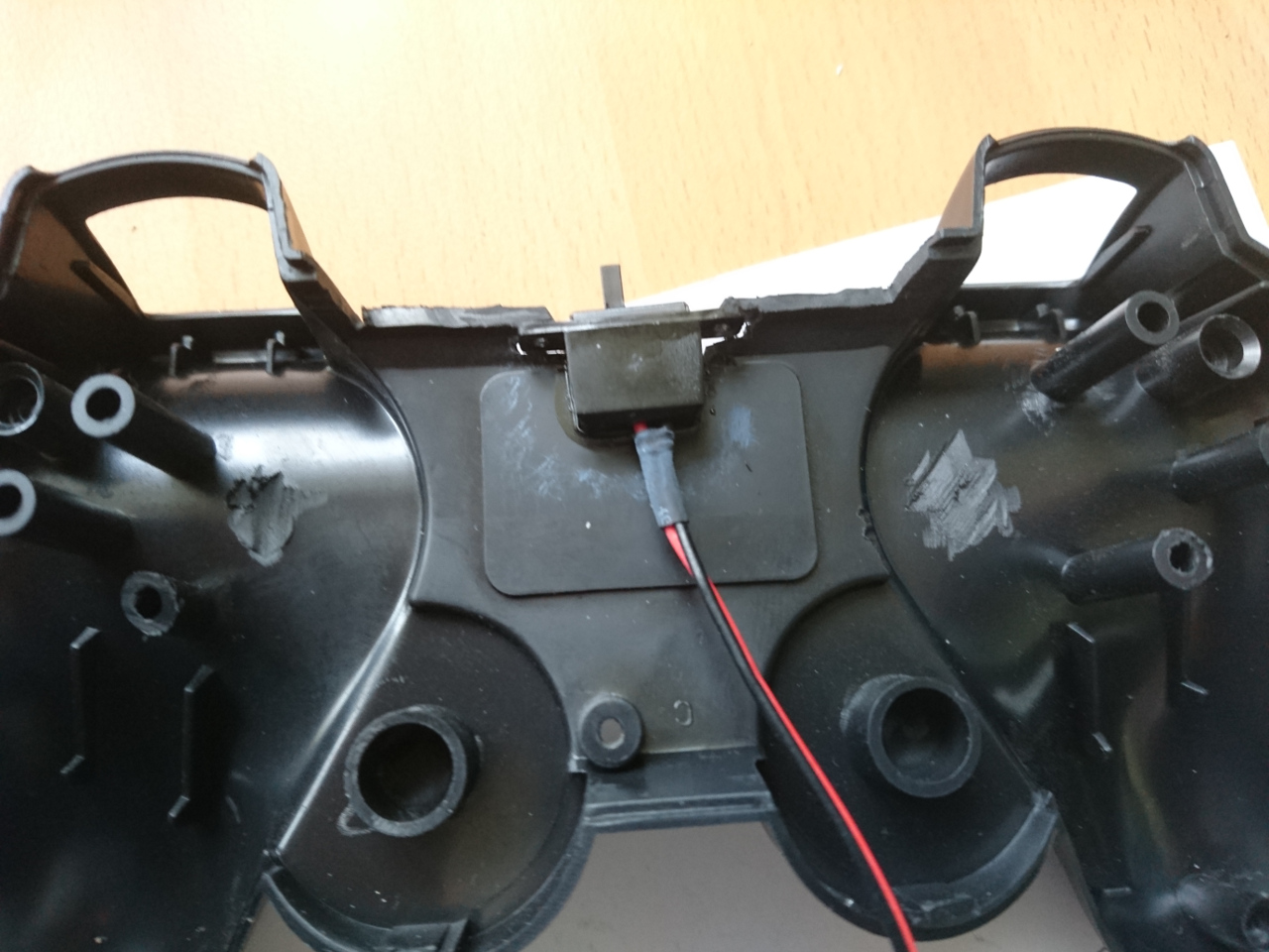
Also, it has two pins where a simple switch on/off (low amp) goes. One our motor controllers came with. (that we had to remove!) So, everything wired up together looks like this: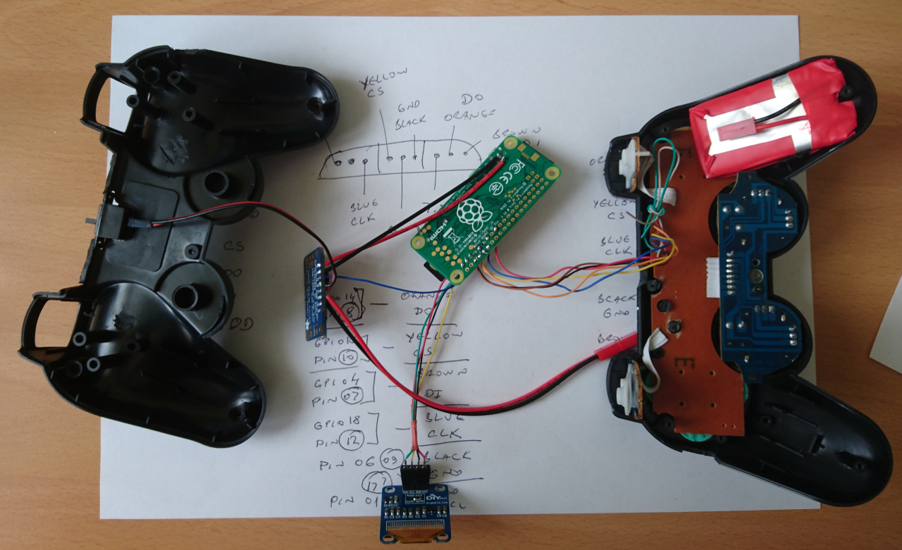
You can see on the picture that some of the internal plastic from the controller was 'filed' down so it makes enough space for the components.
A few screws in and... Well - that was Friday evening and a hour or so on the Saturday. From now on things turned out not to be 100% they way they seemed. Low Battery Output is not 3.3V GPIO compatible output but pulled to battery voltage while battery is fine. And that goes up to 4.2V. But when low, it goes to 0V. And that's not all - even if risking GPIO with higher voltage than usual, connecting GPIO to it messes up with power booster's internal logic and it appears that it immediately, wrongly, detects battery being low. So, that was moment for plan B. Luckily we are not the first to encounter it (see here). Mistake number one was to try to use a mosfet transistor instead which needs much higher voltage on the game and it caused the first cell of the battery used to be over-discharged and as such completely ruined. 5 hours, one NPN transistor and one resistor later, plus some tiny smd soldering we were back on track and and here's the outcome: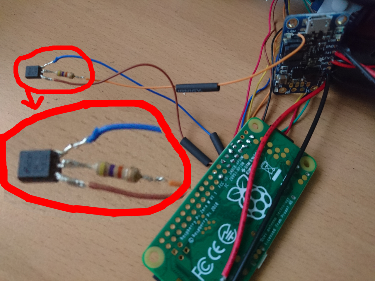 So, back to pack everything back inside and here it is, again, ready to go:
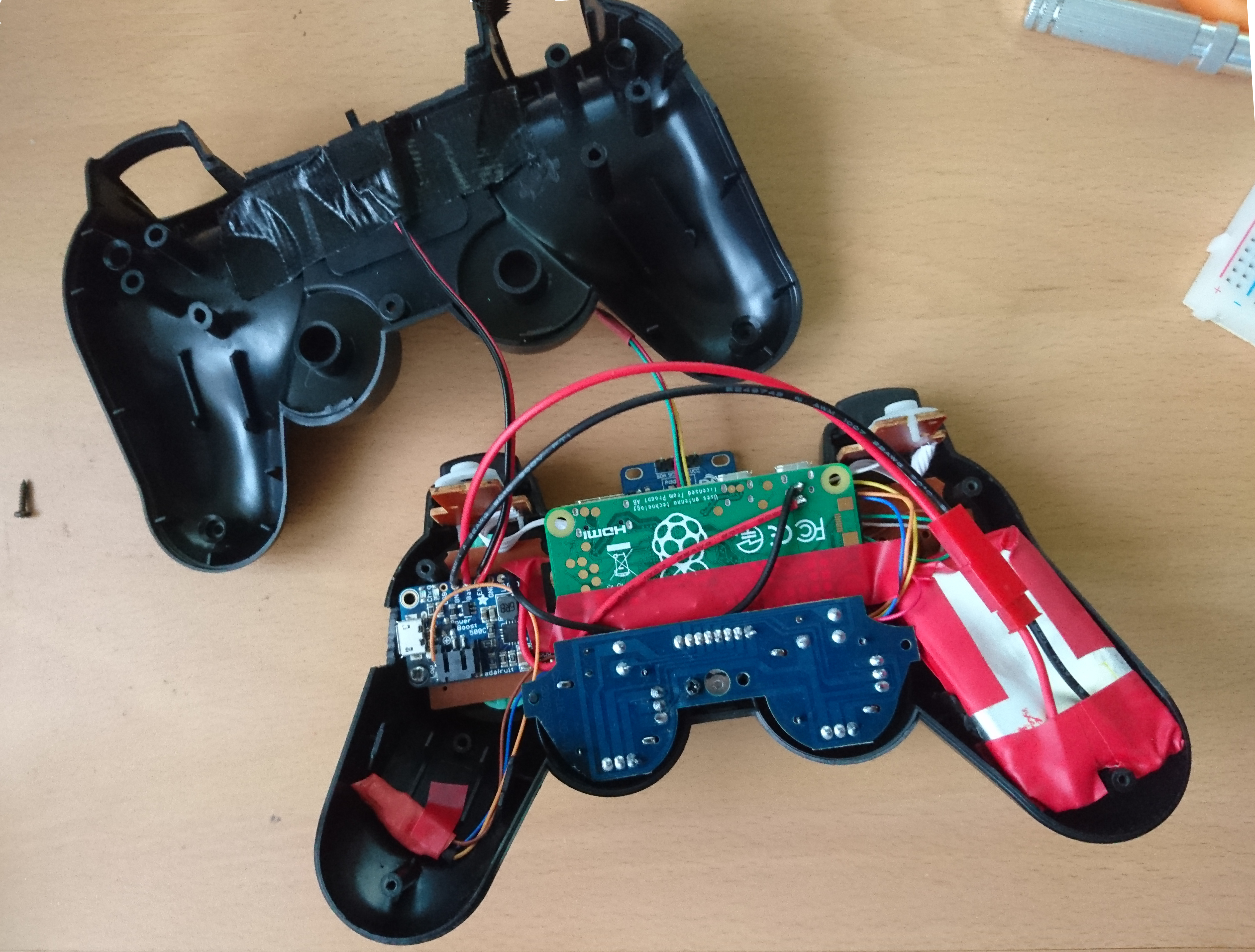
The software at the moment just displays the position of the two joysticks, the cursor keys and all the buttons. And the battery status. Also, pressing select and start together allows PiZero to be shutdown gracefully: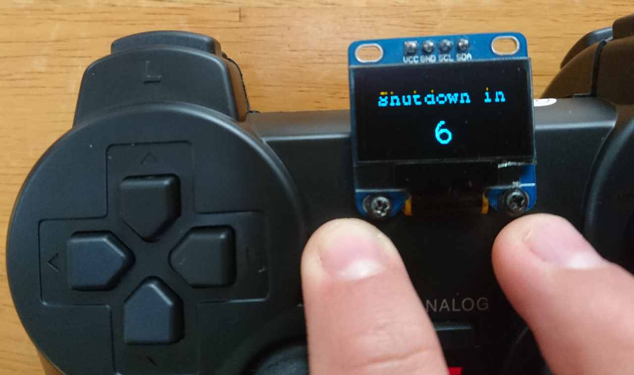 Next is to add menus so we can select which rover to connect to, implement checks if the PiZero is connected to WiFi network and/or a rover and add paho to send appropriate messages to the connected rover. Plenty more distractions - but really good task for students to 'connect' to the rover and add more sophisticates 'moves' to the controller's buttons...
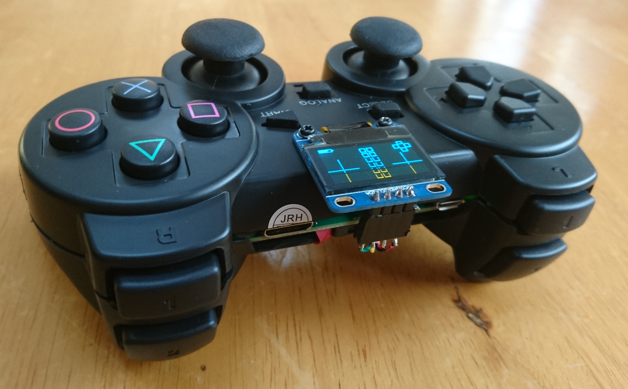
Comments
Comments powered by Disqus