The Making of The Rovers
Then
The cardboard prototype was perfect for getting the approximate size of the chassis and position of the steering servos but not good for rigidness.Original idea was for steering servos to be placed along length of the rover for making it even more rigid. Unfortunately it wasn't the best idea as amount of space on the 'first floor' of the rover wouldn't be used in the most optimal way. Type (and size of the battery) dictated that long and narrow space was needed and servos on the side would have used it all. On the other hand, placing the servos perpendicular left enough space for battery to be placed on its side, on the side of the rover next to the hole for the camera. Length of the battery and size of the servos defined our rover's footprint: 160mm x 110mm.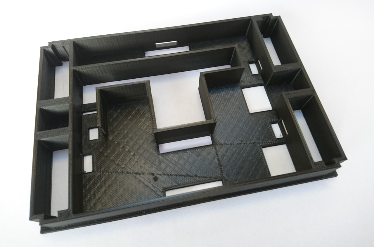 A few prints of the main chassis and we've settled down to exact measures, the position of the Raspberry Pi on the top of it and gap needed for camera to operate under the rover and over.
Next was to use space underneath of the rover for motor controllers, power distribution board and fuse. That part was the most tinkered with - we went through no less than 13 versions of it. Main issue was it to provide enough space for all the component and to have enough clearance between the 'tall' tyres and the corners of it.
A few prints of the main chassis and we've settled down to exact measures, the position of the Raspberry Pi on the top of it and gap needed for camera to operate under the rover and over.
Next was to use space underneath of the rover for motor controllers, power distribution board and fuse. That part was the most tinkered with - we went through no less than 13 versions of it. Main issue was it to provide enough space for all the component and to have enough clearance between the 'tall' tyres and the corners of it.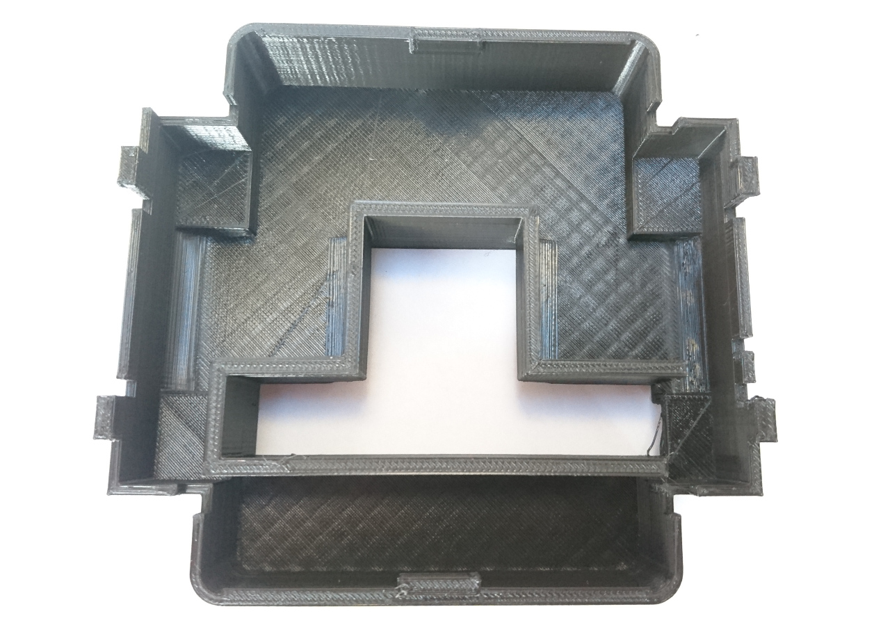 Aside of the main body parts, we designed an arm which holds the camera in position: underneath the rover and completely centrally. With it we could start thinking of the code for following the line challenge as we would be able to see what is directly, centrally under the rover. But as the arm is operated with two servos it can be lifted through the gap on the bottom and chassis and used, sometime in the future, for driving rover remotely using only streaming from the camera to the controlling PC/laptop.
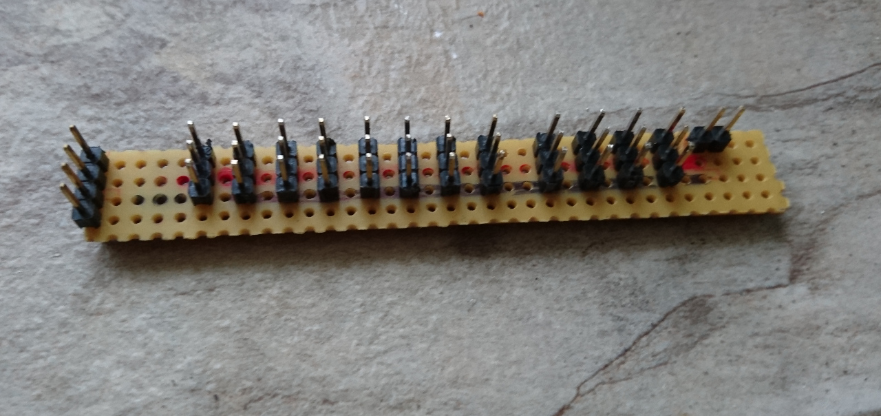
After printing the main parts of the rover, next was to put together a small PCB to connect all the servos to. Also, same PCB involved to hold tiny electronics (voltage divisors) for HC SR04 ultrasonic sensors and small transistor for switching on/off LEDs (needed for lights for the camera):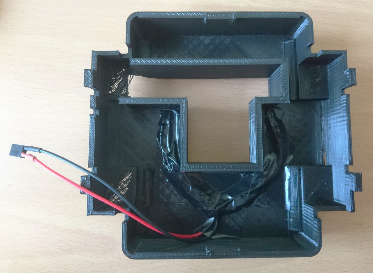
 When all bits and pieces were properly stuffed in the bottom it looks like this. Not a pretty picture but at least hidden from the view:
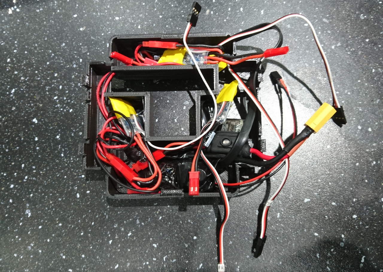 PCB was made of striped prototyping board. It has places for 12 servo connections (2x4 for wheels, two for camera arm and two for 'attachments'):
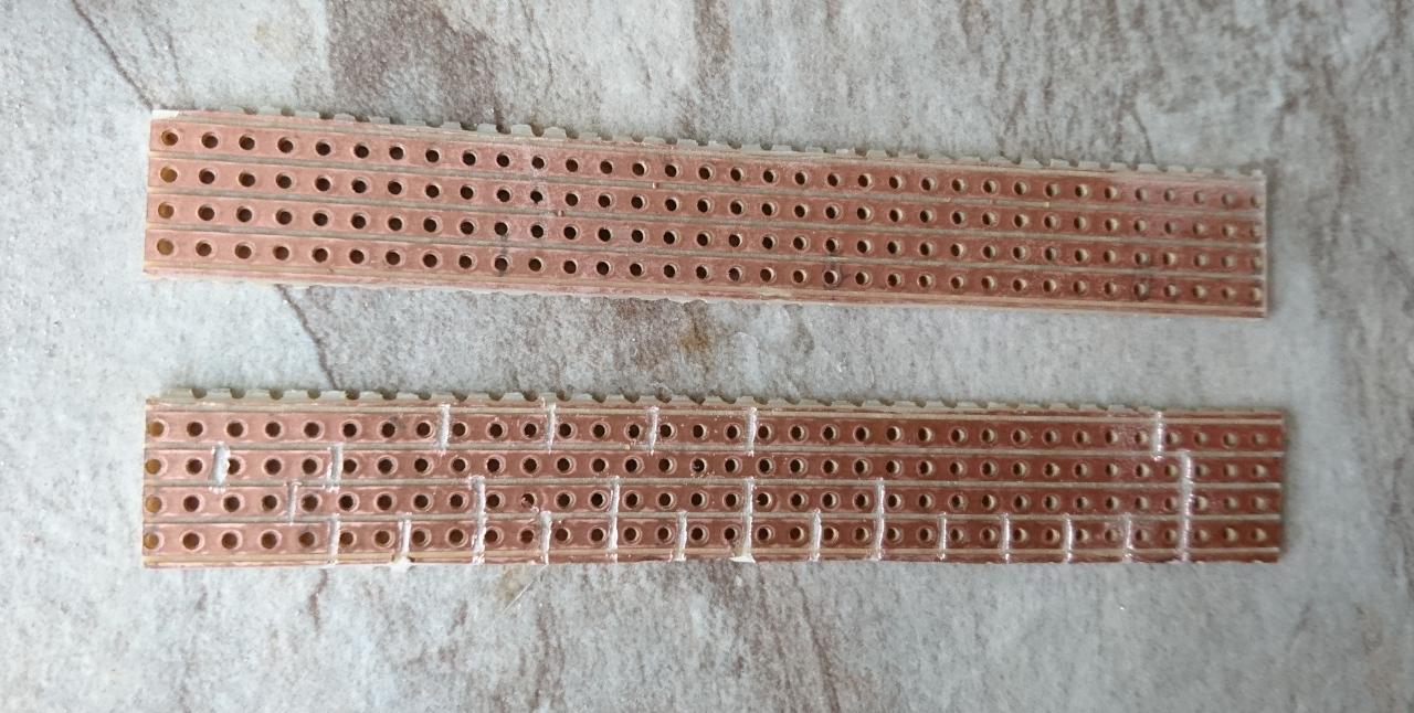
 Old hard drive cable was used to connect Raspberry Pi to the PCB and 9 degrees of freedom (9dof) sensor. Also, on one of the remaining GPIO a switch was attached so we can use it to shutdown our rover without need of using a computer and SSH.
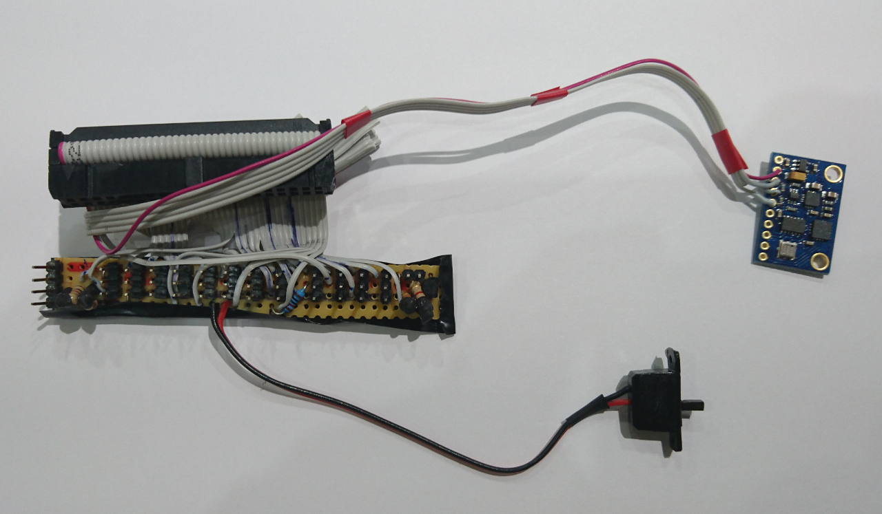 As PCB is to sit below Raspberry Pi we needed to protect it from the bottom:
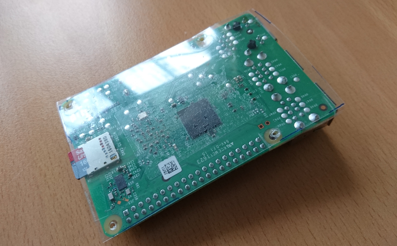 All together made our PiWars rover.
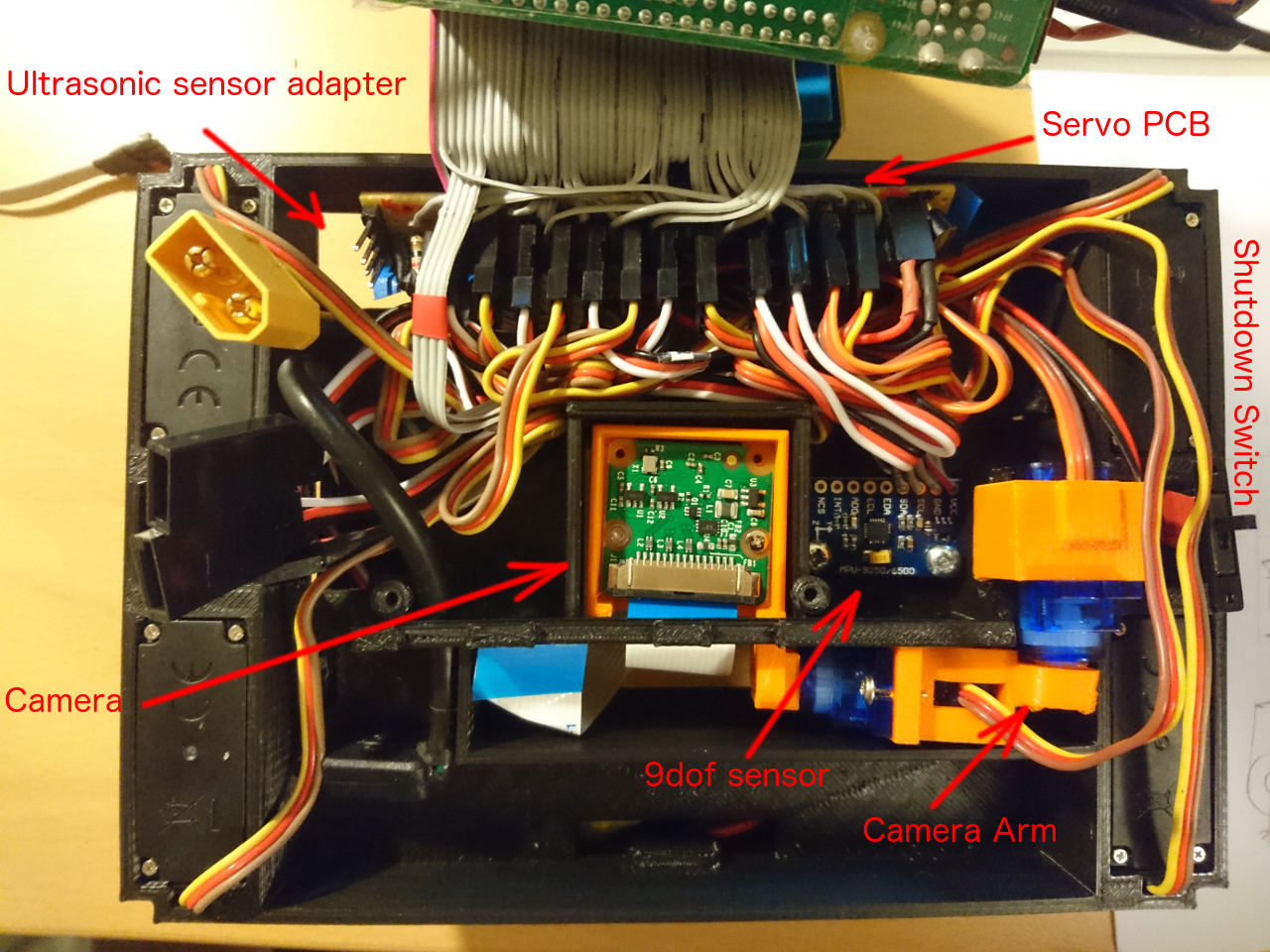
Here it is posing with ultrasonic sensor at the front: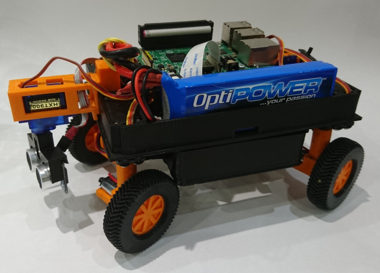 And from the bottom:
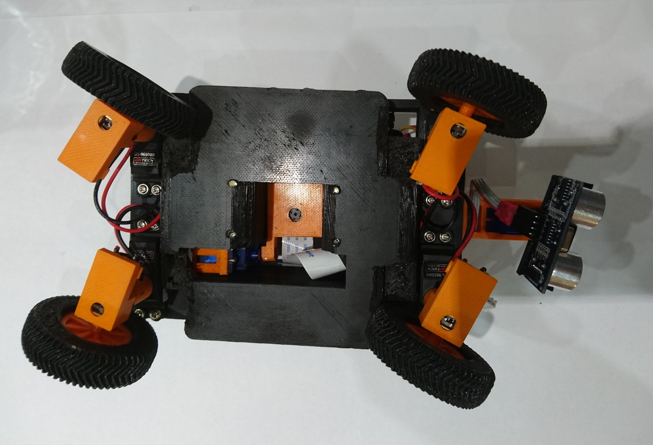
That is how our first rover had been made. Or the second, third and fourth prototypes evolved - it depends how you look at it.
Sponsors
This is perfect spot to stop and mention how did we get to have our rovers and sponsors that helped us build them:
![]()

Original idea was to have at least two rovers so we can stage our own PiNoon trials and, if possible, a third one so we always have a spare. Also, it is much simpler to work in parallel at our club sessions if three separate groups of students can have their own rover to work on. And here they are: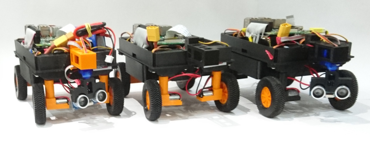 So, I would like to use this opportunity to again thank Creative Sphere for letting us use their 3D printer and initial bits and pieces (LEDs, screws, small components, RPis, game controllers, plenty of PLA filament, and many more little details); Vectric for printing out a few bits for us, motor controllers, 9 degrees of freedom sensors, batteries, skittles set and such and Black Pepper for loads of servos and Raspberry Pi cameras for all three rovers. And for all the support otherwise. It not only helped us prepare for the PiWars competition but help us build base for all the further robotic endeavours on the Games Creators Club at Kenilworth school.
Now
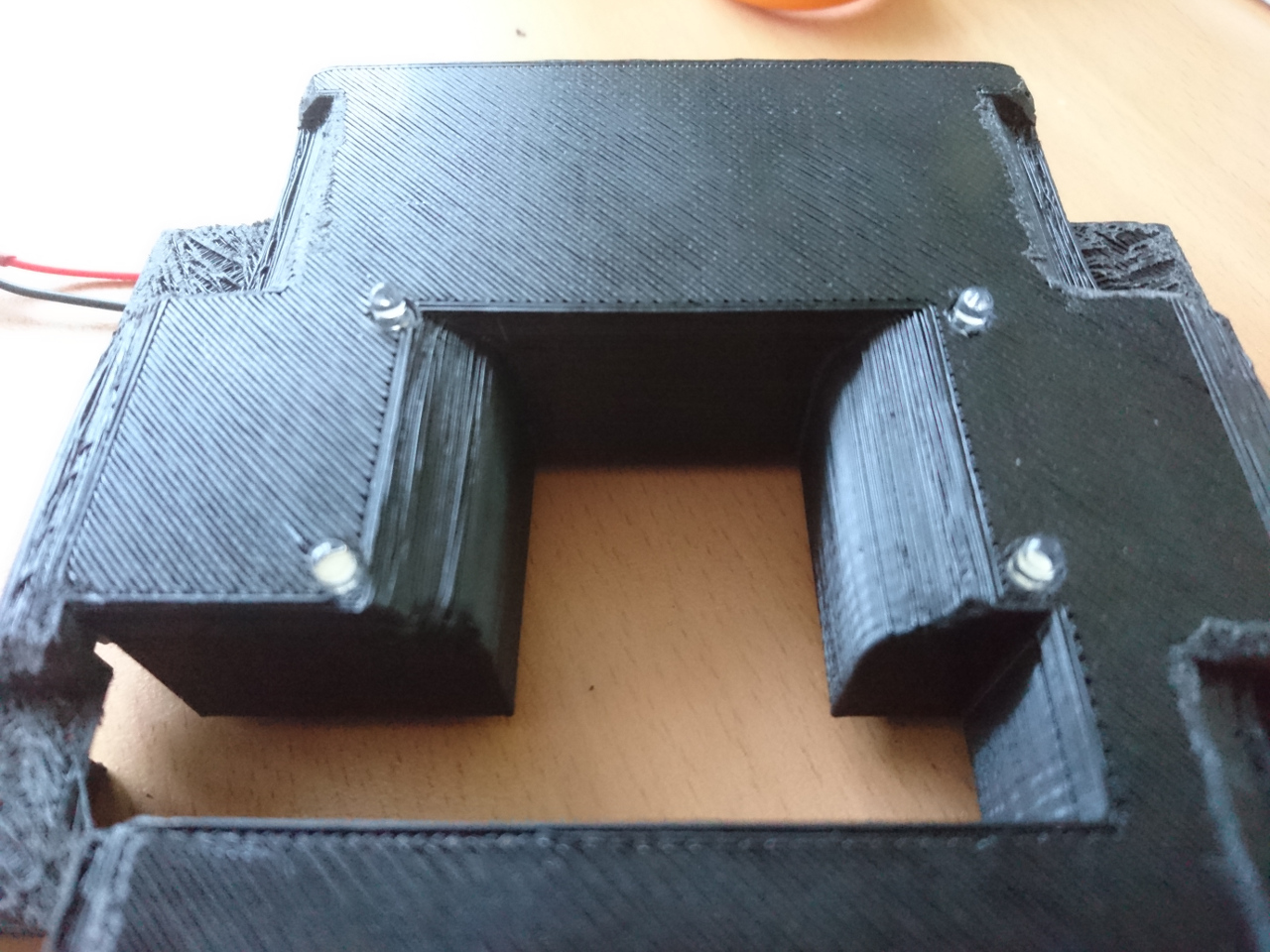
One of the last problems we needed to deal with was bottom of the rover and the way it was attached to the chassis. The bottom part would just fall off during our PiNoon duels and it was real pain putting it back together. It desperately needed fine tuning with the tabs which latched on to the chassis and a place for proper screws. Like one on the picture below: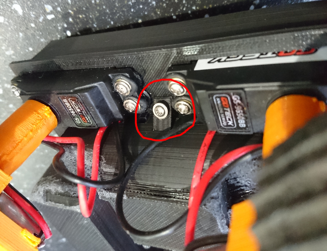
Another issue was the falling of the wheels. It is quite embarrassing when in the middle of our local PiNoon duals, wheels would fall off the rovers. Or during the straight line run where it would often finish balancing on three wheels only. We started with the idea of a D shape hole that printed off in the middle of the wheel and made quite a snug fit that it would be enough for the wheel to stay on. Well, it turns out that it is not the way real world works. So, now we've redesigned it so wheels have a screw that goes to the flat spot of the motor axles. It works much better now, hopefully.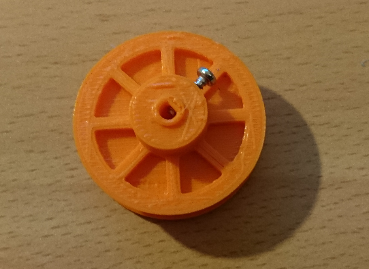
Next time: more about the attachments and sensors built into rover.
:)
Comments
Comments powered by Disqus