YGCC Rover
GCC Rover
As this can be last post before the blogging competition is closed let's use this opportunity to describe how far we managed to go with our rover and maybe mention how far more we would like (probably for the next year).
But before that is very important to say that this journey was really interesting and fun. And hard and frustrating at moments. But it was worth it!
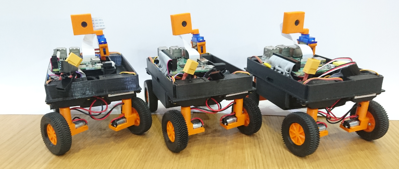
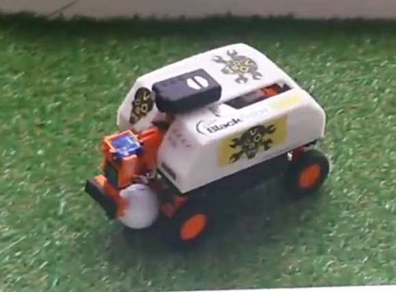
GCC Rover M18 aka 'Plan B'
As the 'name' suggests it was mostly composed with 'Plan-B' options and solutions. It really forced us to think on our feed and make hard decisions. At the same time - all those second best options we were forced to pick are really perfect points for improvements, especially now when we have 'working solution'.
First Tier - Wheels

This rover has four wheels where each can rotate 360º. Inside of wheel hubs we have little (dual) H bridge (wired with both sides in parallel) controlled by ATmega328p µController. The same µController reads AS5600 rotational sensor (wheel movement feedback - odometer) and nRF24L01 2.4GHz transceiver to communicate with the main Raspberry Pi. Also, it has 'plan-B' micro geared brushed motor. Motors are geared for 300RPM @ 6V. Wheel hubs house 65mm diameter (~210mm circumference) wheels where last 2mm are printed with ninja-flex flexible material. Our finger in the air check gave result of at least 0.7g for tyre grip. Beside that, each wheel has 5mm magnet in the centre so AS5600 rotational sensor can work.

On the outside wheel hubs have copper rings for transferring power to them. Power is transferred by brushes. Each wheel has two set of brushes - just in case that one is not making good contact. This tier is powered through XT60 connector which connect it with the tier above (where battery is connected to).

Also, on that level we have 4 little motors (similar, but just geared for 200RPM on 6V). Again, they ended up being 'plan-B' option. Currently they are the fastest that have enough torque to turn wheels. They rotate wheel hubs:

Their current speed is around 250º/s at the full speed (there is 0.1s or so before they can reach it).
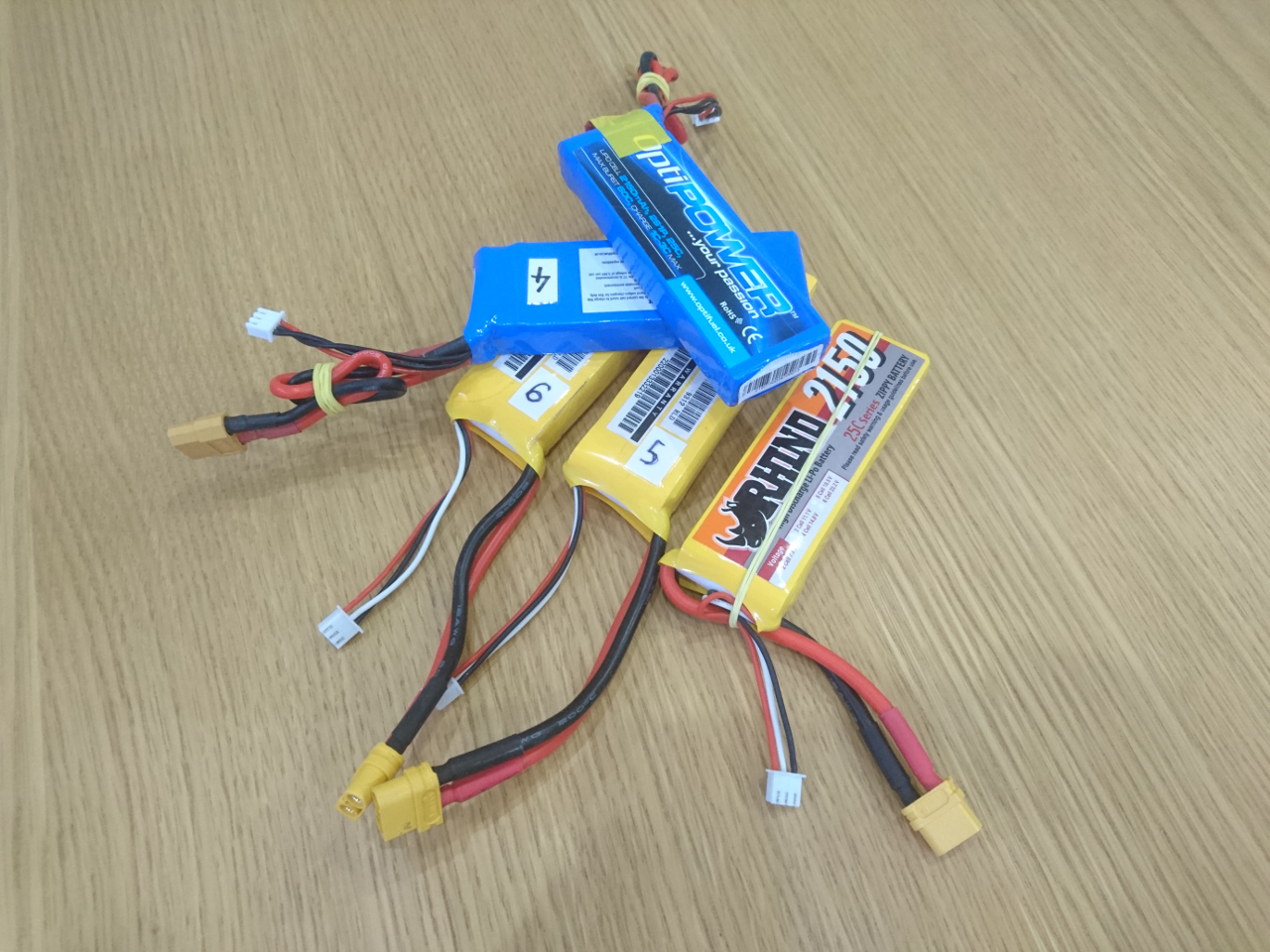
Aside of little motors there is space in the middle of the rover for the LiPo battery:

Middle Tier
Middle tear has two dual H bridges on the bottom side which are connected with micro deans connectors to steering motors. Also, middle tear plate has hole, just below the main Raspberry Pi, pretty much in the centre of the rover, where the commanding nRF24L01 24.GHz transceiver is mounted.

The next important thing on that tier are 4 AS5600 rotational sensors, one over each wheel hub. They report back position of each wheel hub. At the top of the wheel hubs are tiny magnets which are read by those sensors.

On this tier we have the main Raspberry Pi, 3B+ (with heat sink!) and satellite Raspberry Pi Zero which is charge of steering wheels and communicating with µControllers in side of wheel hubs. Next to them is DC-2-DC power supply of stable 5V for Raspberry Pies and other sensors and a board for various i²c devices (as explained here and here). Main Raspberry Pi and Pi Zero are connected through USB cable.

Top Tier
Here we have top plate which, on the inner side, holds 9 degrees of freedom sensor, Adafruit's sensor (gyroscope, accelerometer and compass); little mono amplifier and a speaker. Also, we can say that 3.5" touch screen with resolution of 320x480 belongs to this tier, too. Top plate, also, has two slots for 'attachments' and 8 slots (at 45º apart) for Raspberry Pi cameras.

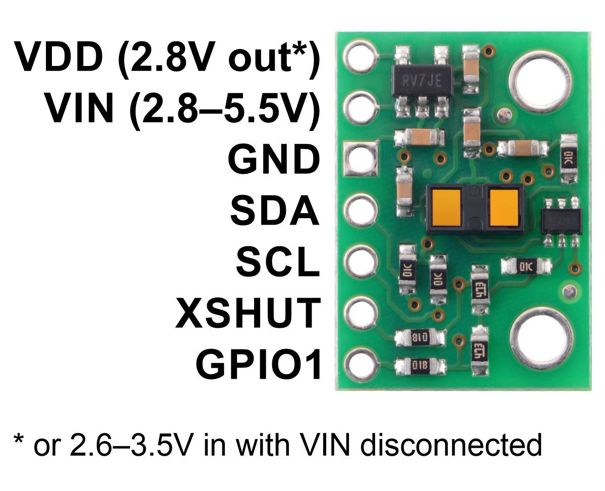
Worth mentioning are VL53L1X time of flight distance sensors that are, really, mounted on four 'corners' at the bearings wheel hub levels and four recesses (not really visible on the picture). They provide 360º distances information at each 45º.
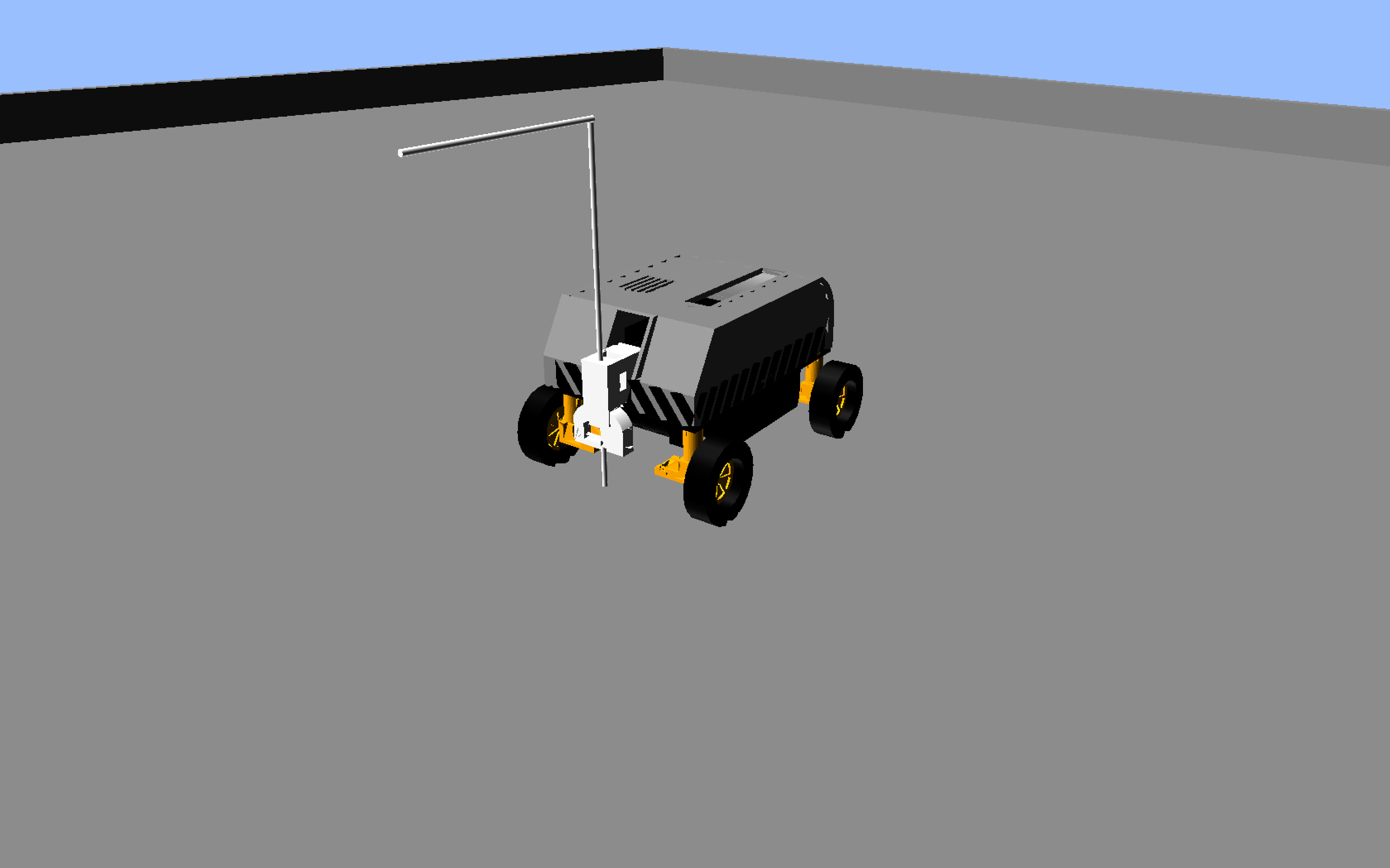
Also, at the 'front' we have place for PiNoon and Spirit of Curiosity challenges attachments.

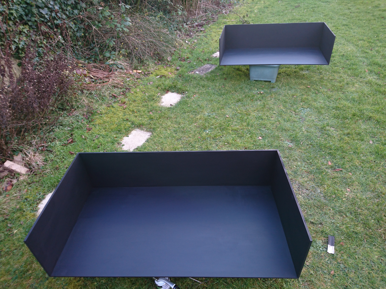
Bottom And Stand
Since we've been through all the hardware of our rover it would be shame not to mention something that's not strictly on the rover but has been extensively used while working on the rover: the stand. THat tiny piece of 3D plastic was one of the best things we've done in last three years of PiWars engagements. It allowed easy access to all sides of the rover letting it freely spin around Z axis while keeping wheels off the ground and without any obstructions.

Aside that you can see very thin gears guard, too, which, at the same time serves as a guide for the stand. Tiny gear in the middle has its own mysteries. It is there for...
Software
As mentioned many times our rover is 'powered' by PyROS (Python Rover Operating System) - a python service started by systemd unix service, which, in turn, provides interconnectivity between PyROS programs, agents and services (simple Python programs which can use pyroslib). PyROS services are started at the start up of the PyROS, while agents are sent by client programs (usually running at our laptops) to be execute don the rover for particular challenge. We've already written a lot about PyROS and quite a few aspects of it.
Currently our rover on main Raspberry Pi runs following services:
-
discoveryservice - allows our rover so be seen by pyros command line tools and client programs -
shutdownservice - shuts down Raspberry Pi on demand. It can be triggered by MQTT message through client app, touch screen, pyros command line tool. This service will issue MQTT message for satellite Pi(s) to shutdown and wait for usb(x) (usb0, usb1, ...) network interfaces to disappear denoting that those satellite pies have shut down and only then progress with shutdown of the main Raspberry Pi. -
wifiservice - allows easy set of wpa_supplicant WiFi networks -
storageservice - similar to windows registry - stores key/value pairs to a file (persists them) and reads them back over MQTT on demand. Also keys are in a form of paths. Wheel calibration details are, for instance, stored through this service. -
screenservice - service that renders nice UI on rover's touch screen. -
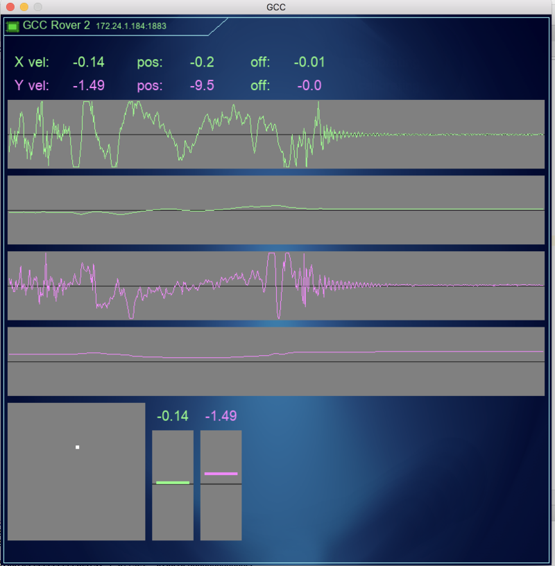
telemetryservice - service that collects telemetry data and stores them in memory. There are client programs and command line tools that use such telemetry data. -
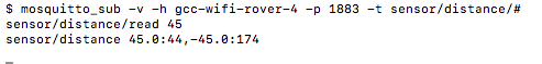
vl53l1xservice - as name suggests it reads 8 VL53L1X sensors, processes data and provides them through MQTT -
positionservice - similar to vl53l1x service, it reads 9dof sensor and provides positional data (heading for instance) -
powerservice - collects stats of how much power rover has consumed so far. Aside of measuring time Raspberry Pies are on, it collects data from satellite Pi Zero about wheel power and steering motor power consumption. -
cameraservice - when invoked fetches stills from the cameras, processes them and sends results to MQTT topic -
joystickservice - monitors connection of bluetooth (or otherwise) controller and when present uses it to control wheels sending MQTT messages to drive service -
driveservice - similar to M16 rover, it consumes MQTT messages which tell rover how fast to go and where (or to steer or rotate) and translates them to individual wheel's position and speed messages
Aside of service there are a few 'libraries' provided through PyROS:
-
pyroslib- way to accessing MQTT (paho-mqtt) messages - sending them and/or subscribing to topics to receive messages. -
storagelib- utility methods to access storage service
On satellite Pi Zero we have following services running:
-
shutdownservice - similar as above, but only shuts down current Raspberry Pi -
telemetryservice - local telemetry service to store telemetry data in local memory -
wheelsservice - service that steers wheels driving H bridges and reading AS5600 rotational sensors using PID algorithm. Also, same service is responsible to talk to master nRF24L01 2.4GHz transceiver to talk to wheel hubs' µControllers - sending them required speed and reading current position of wheels (odometers)
Same as on the main Raspberry Pi we have pyroslib and storagelib provided to the satellite pi.
Prototyping
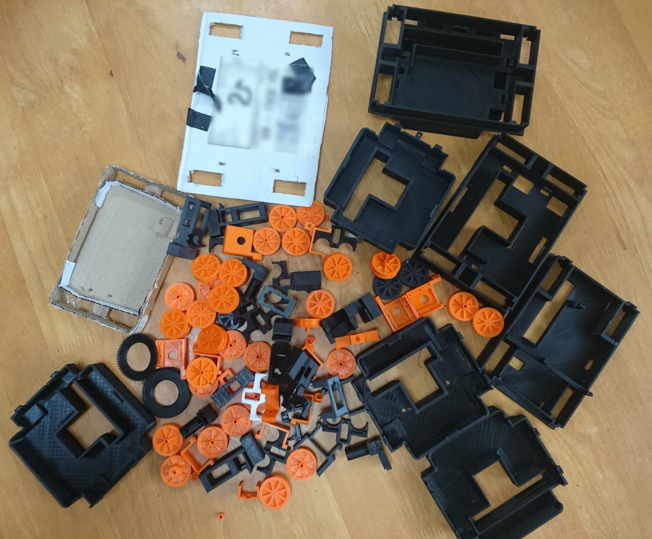
This rover, due its complexity, needed a lot of prototyping. I mean really a lot:

That's over 1.5kg of plastic and other bits inside...
Conclusion

This years rover ended up being quite complex. It has almost ultimate mobility with ability to rotate, go sideways and do all of it while constantly rotating. Wheels provide movement information feedback (odometers via rotary magnetic sensors) with all around distance sensors along positioning system (9 degrees of freedom sensor) provide that more informatino than we could have handled this time. PyROS got extension and now supports cluster of Rapberry Pi computers allowing them all to work together using MQTT for communications. Aside of 'important' stuff it finally gained touch screen with SciFi inspired theme GUI and audio feedback allowing playing sounds and delivering feedback in a form of a computer generated speech. And all packaged in a nice, stylistic body.
Still there's plenty to do: main motors are tiny motors used on our previous rovers which where less than 1/3 of this rover's weighs and steering motors steer wheels at the edge of usability. We didn't get to implement properly power management where whole Rover can shut down different portions of it and/or completely itself, while constantly monitoring battery voltage and current through it. Also, interior is organically grown - wire management is at prototyping stage, PCBs rudimentary. It would be really cool to try to use PCBs in wheel hubs so they have dual purpose - hold electronic components and act as wheel guards at the same time.
Software wise - it would be really nice to tighten control loops and fine tune PID algorithms. Also to provide better representation of the real world combining wheel orientation feedback along with odometer to calculate how much rover really moved and where, along with distance sensors and positioning system (gyro, accelerometer and compass). And use that data to superimpose over virtual representation of the concrete challenge. And for challenges maybe to replace some of the coded behaviours with ML and neural networks...
There are so many possibilities! So many things to improve...


 Tiny geared motors used in the body for steering are as well "Plan B" motors. The original idea was to go with geared micro stepper motors but that caused a few issues: they weren't fast enough, they were strong enough and there was an issue if driven too fast - there wasn't a suitable feedback that motor didn't really move whole step as required. Too many little problems that were supposed to be fixed. The original idea was that wheels would have some 'starting point' a contact to denote particular position or tab to cut IR LED/IR Photo Diode setup similar to old fashion mice (there was a wheel with slots moving in the middle of such setup). Wheel would at the start up move to such position and after that counting steps we would be able to say exact position of the wheel. But, if stepper can miss a step - whole idea would fall through as wheel might end up being in completely wrong position to what system believes it is. So, AS5600 + simple DC motor is solution forward.


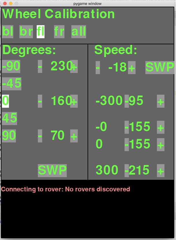
 It seems like a really nice and easy chip to communicate with and works 'out of the box'. First it needs a button sized magnet placed really close to it (see out wheel design), 4 wires connected to the µController (GND, VCC, SDA and SLC) and, what we learned hard way, DIR connected to GND or VCC to determine the 'direction' that the AS5600 will report. Doesn't matter what we select for the direction as we'll easily handle it in the calibration process on the Raspberry Pi.


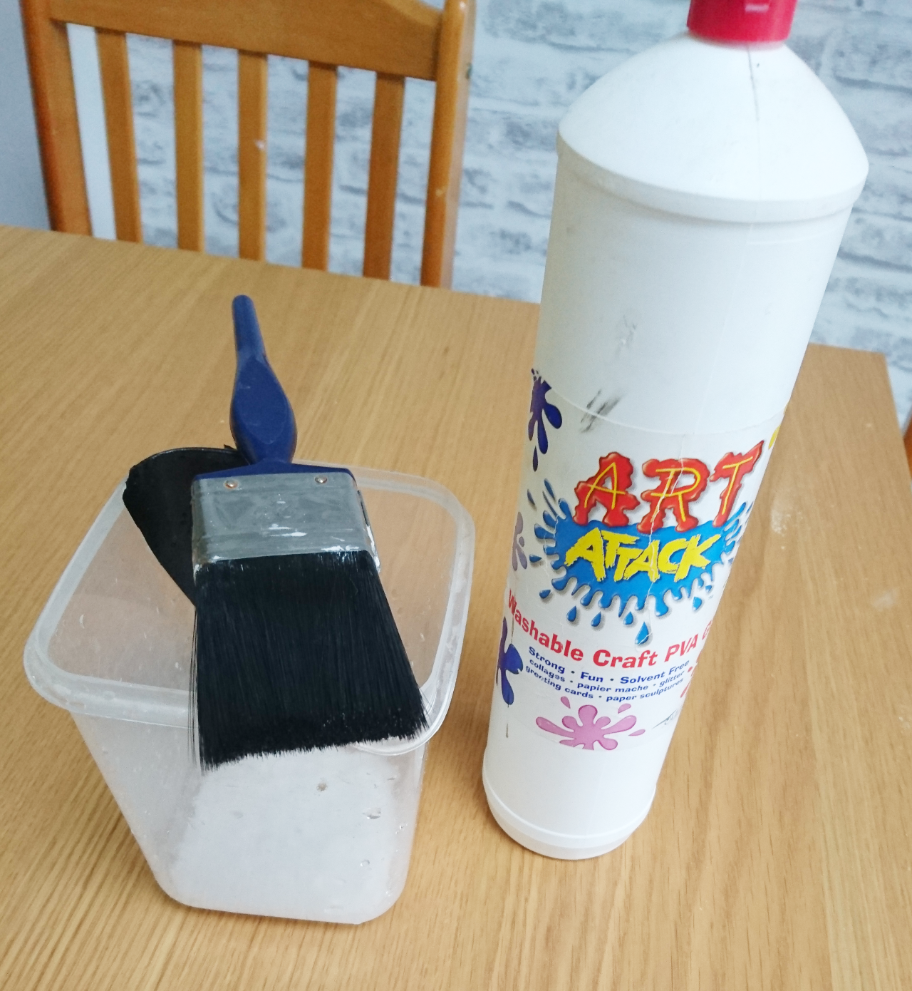
 We've seen that carbon brushes do not work for us. Not with DC power we are trying to deliver to the wheel hub. So, here we go with alternative solution - using copper wire with some springs to mimic the action.


 For wheels to turn (steer) 360º we cannot have wires going directly to motors and get twisted. Original idea was to go with a ready-made slip ring like this:


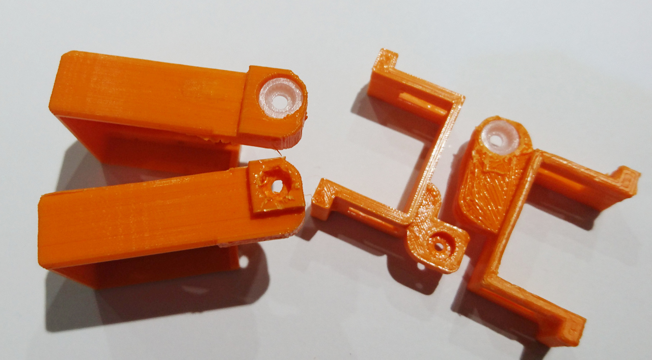
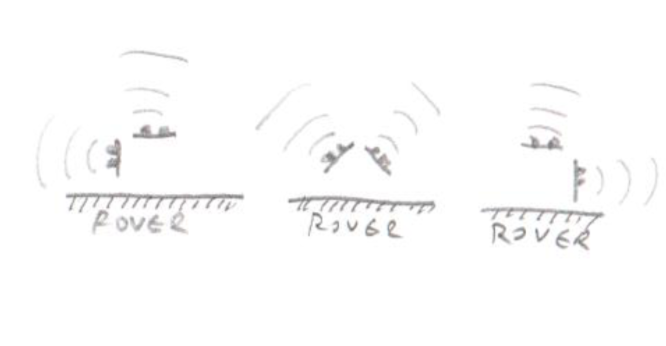 Left and right orientations are exactly what we needed this time.

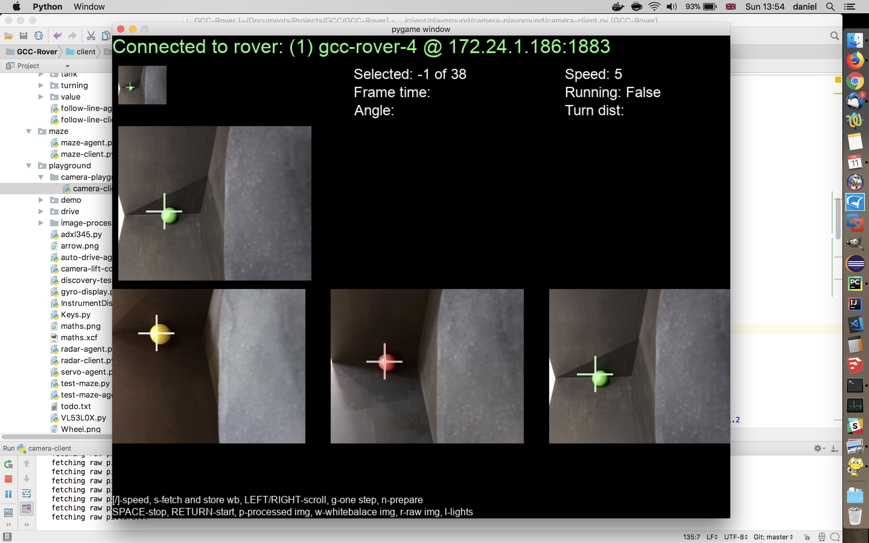
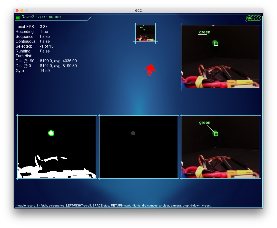 The left image is of the found contour, middle of mask applied to the hue channel (see above what hue was looking like as complete) and last image is the result... well, for looks!
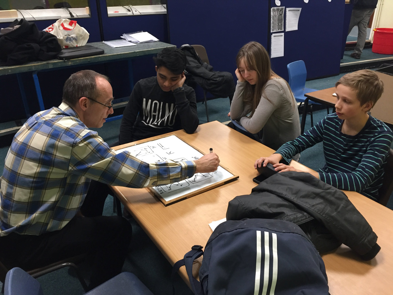
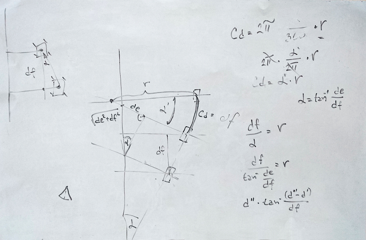
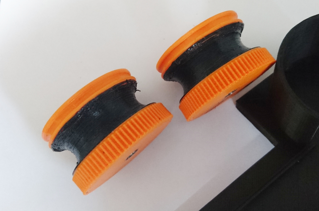
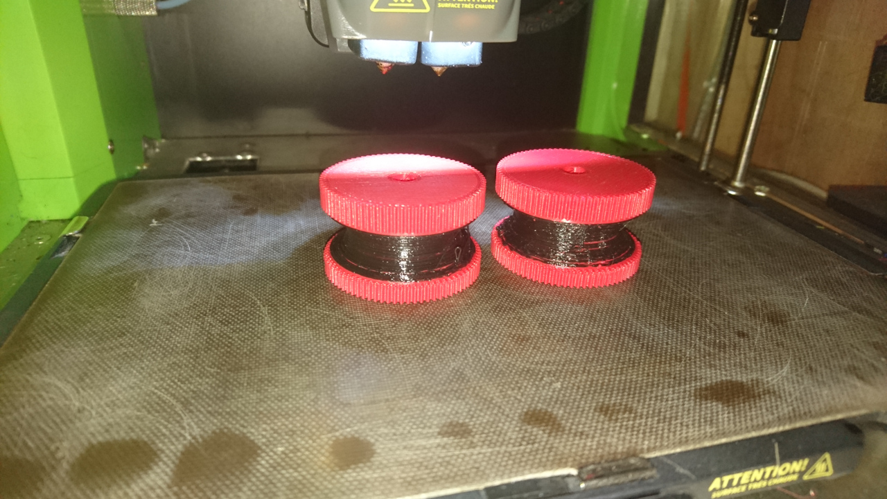
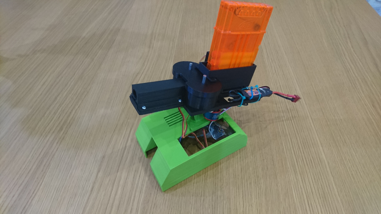
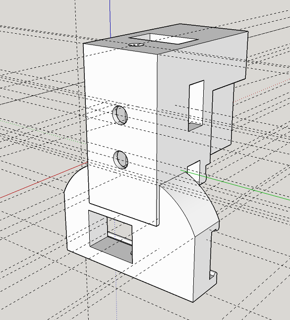
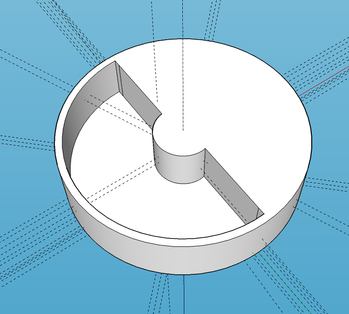
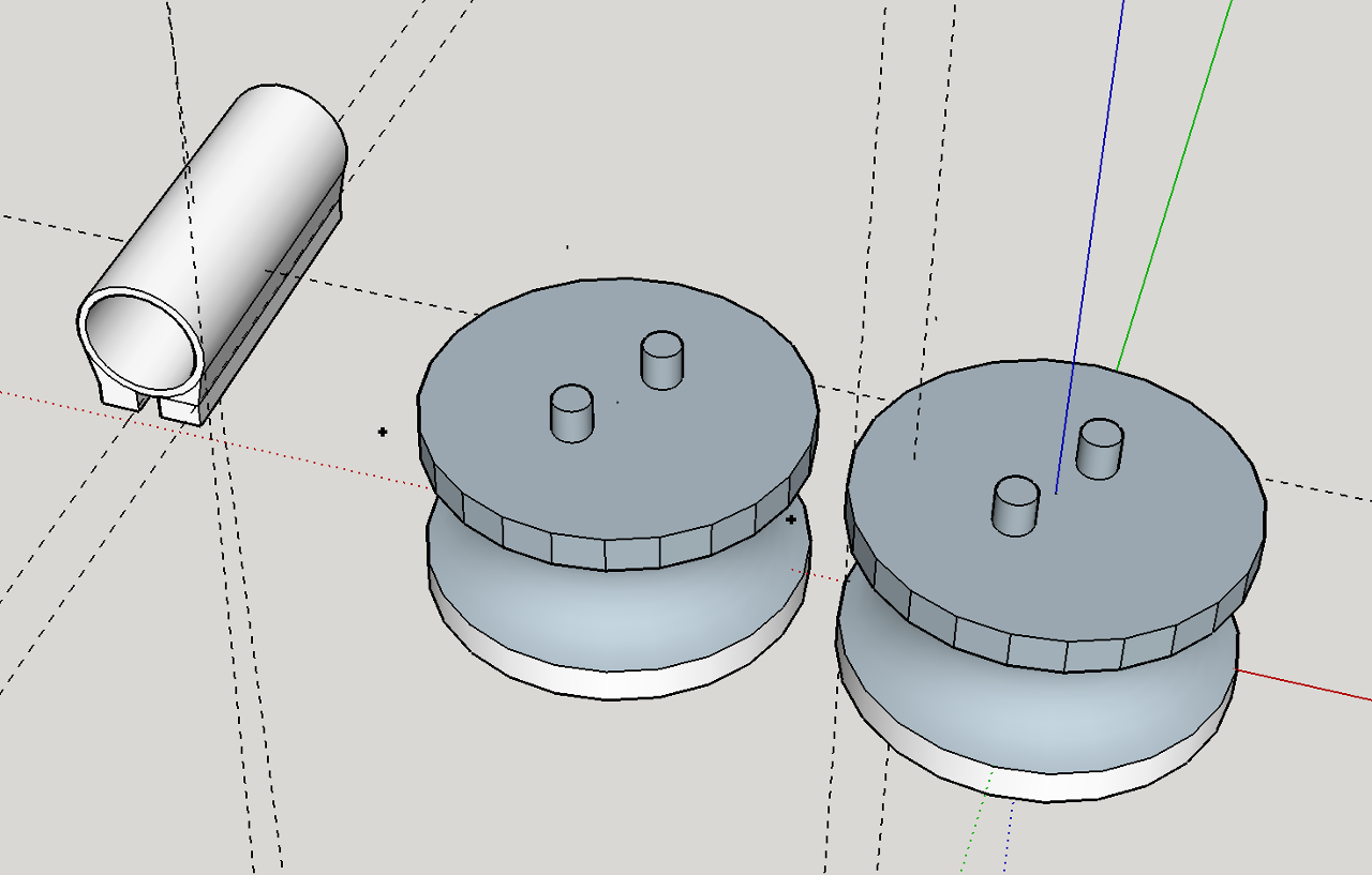 The nerf dart would be somehow delivered in between two spinning cylinders and would be then propelled forward through the barrel. We started with designing a concave cylinder in Sketchup first as it seemed to be hardest challenge of all. Fortunately it wasn't half as hard as we thought.
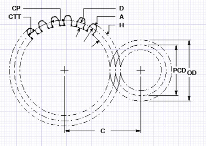
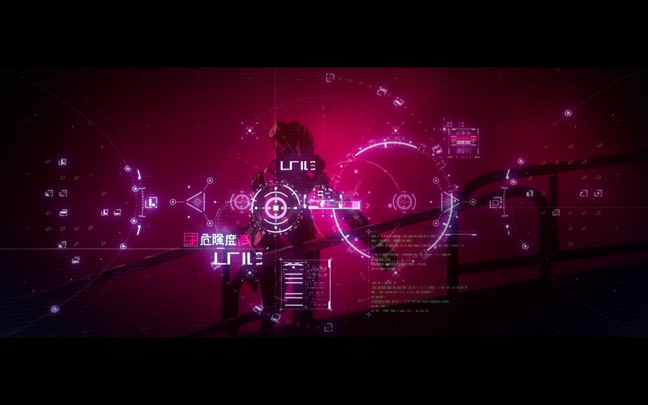 Still frame from the anime
 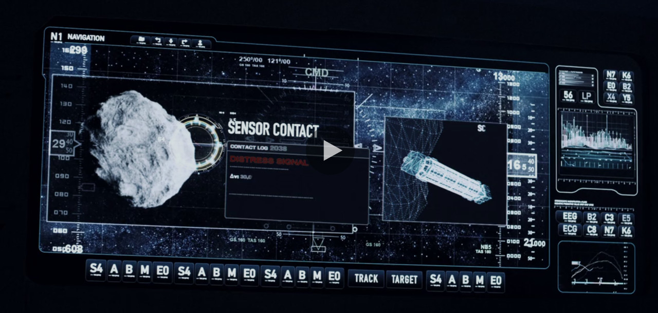 Still frame from the TV series
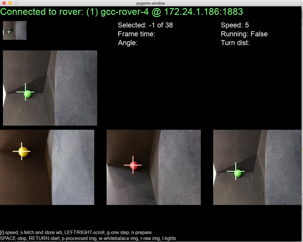
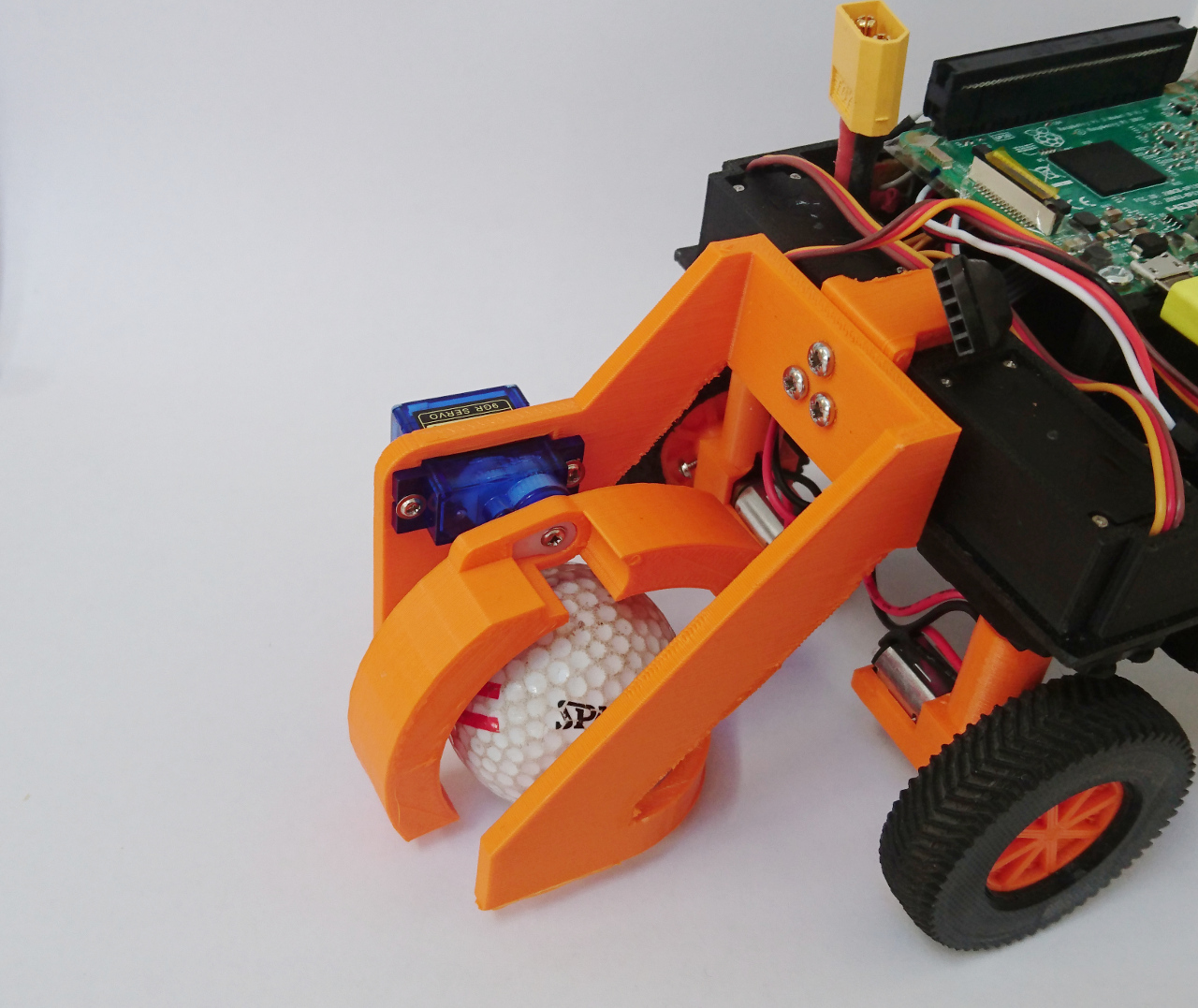
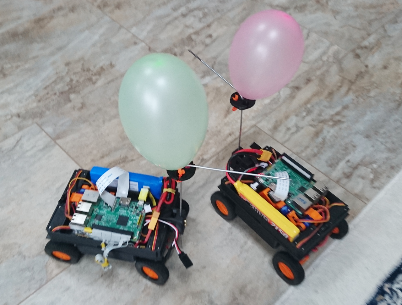
 Also, it seemed that the best results others achieved were when they had some way of 'capturing' the ball.
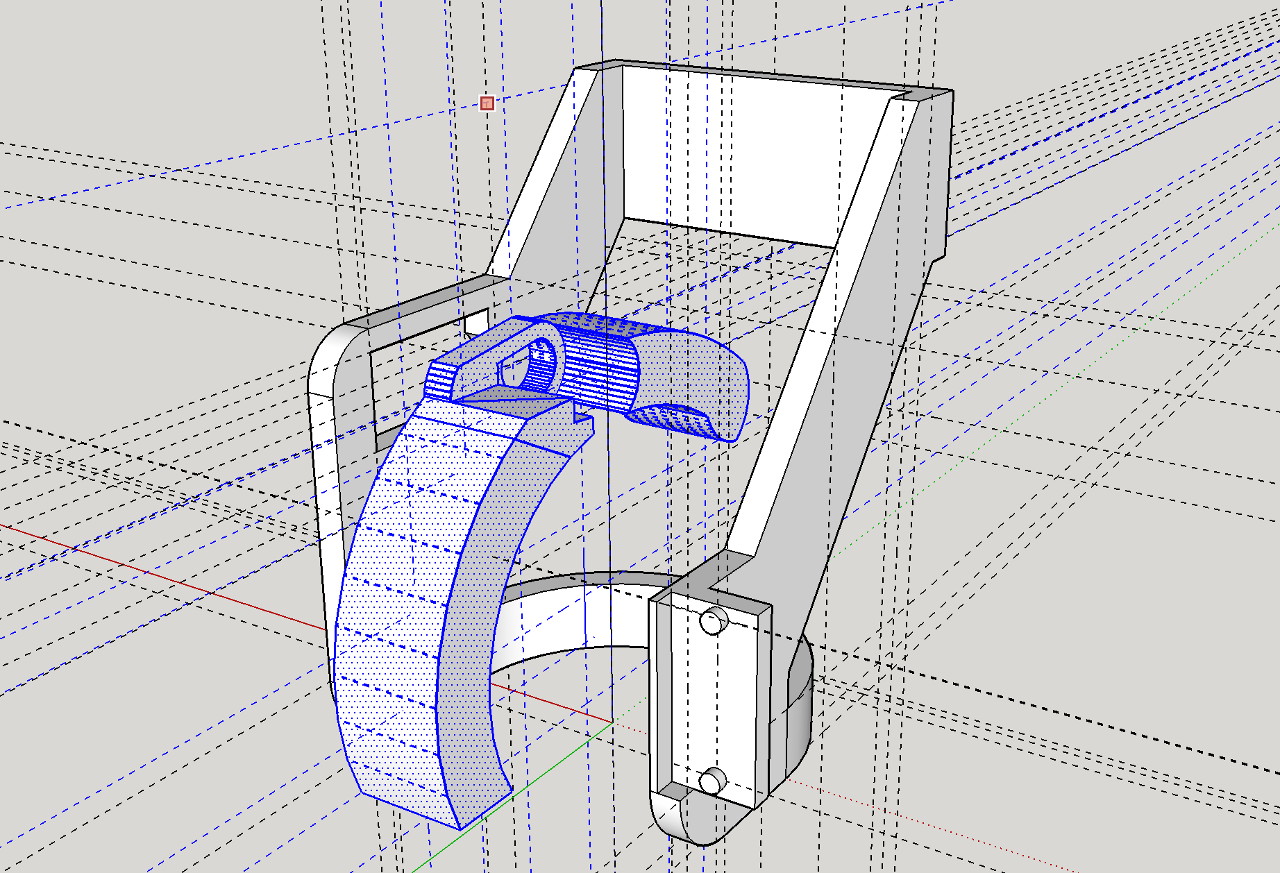
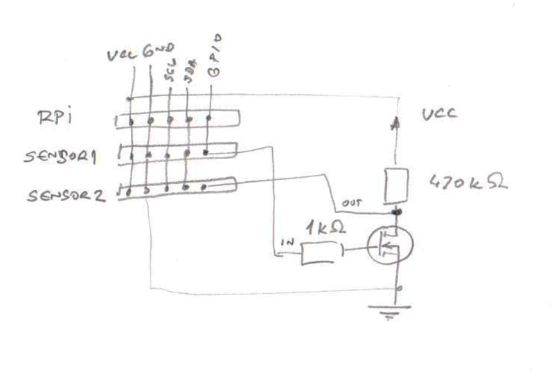 FET transistor 2n7000 (which, btw, I somehow had in box of spares) seemed to be ideal for the 'not' gate.
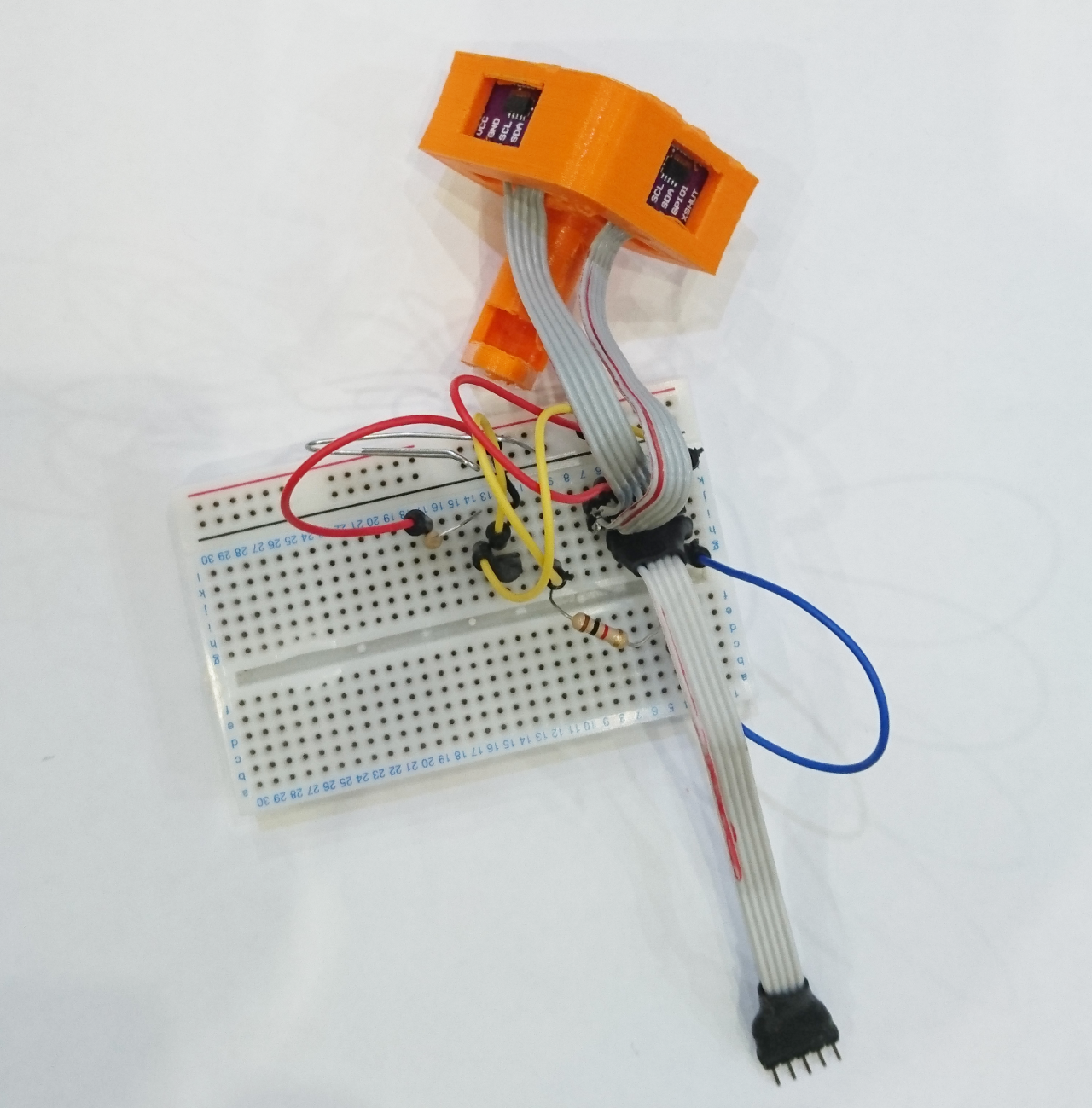
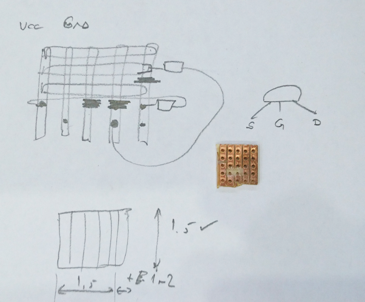

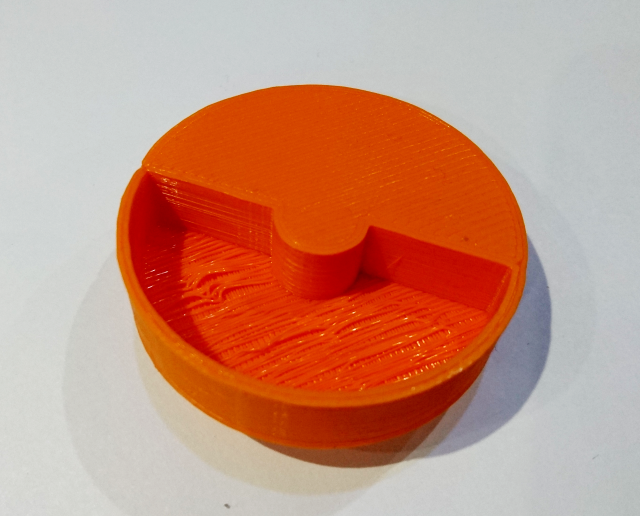 Next was a wheel to help us calibrate the (non load) speed of the motors. It is half filled in and half 10mm indented - an attempt to use same distance sensor for calibrating speed of the wheel. The idea is to put the sensor at some close range (10-20mm) and spin the wheel, counting how many times a second it measured the shorter distance to longer distance. Its target speed can be 120RPM, which is 2 times a second - and the default VL53L0X 'time allowance' is 33ms, we should be able to do 30 samples of which 15 should be shorter distance and 15 longer. The software for it is still pending.
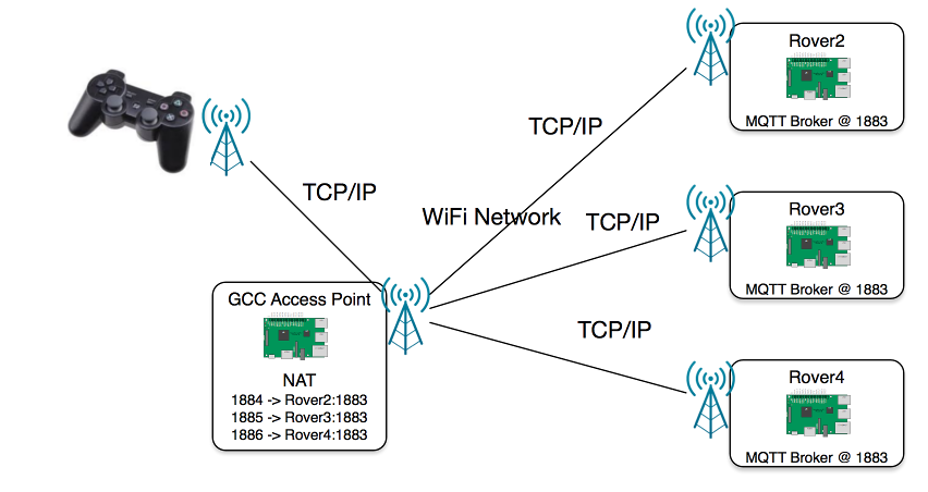
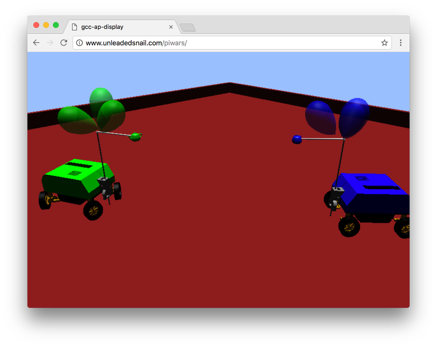
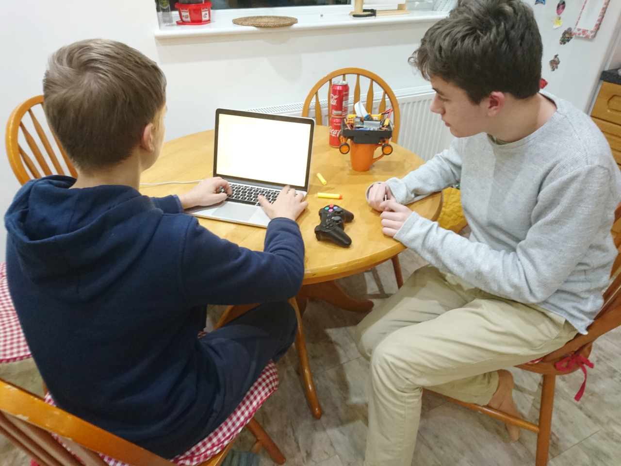
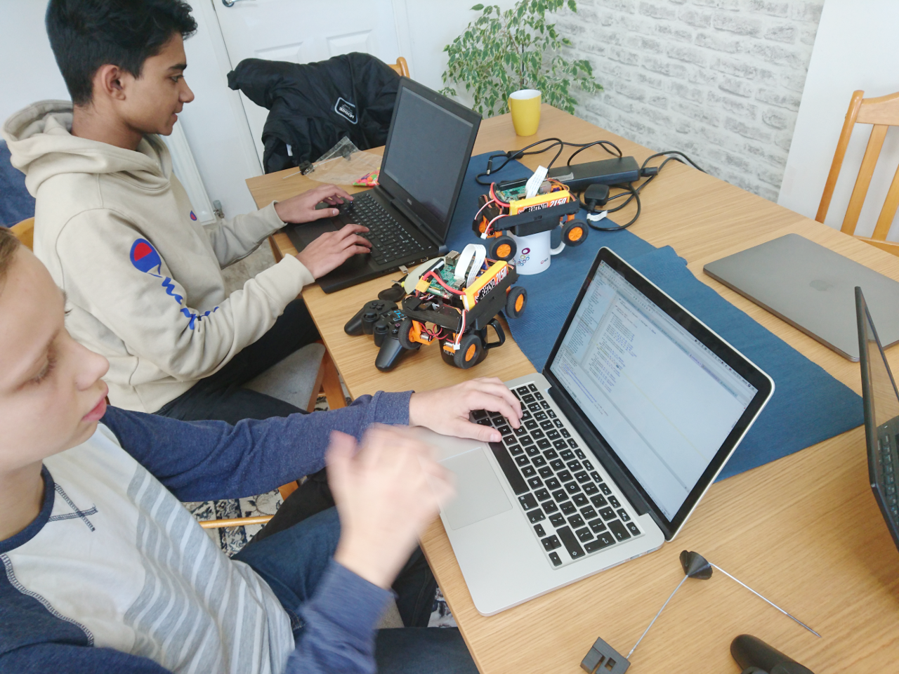
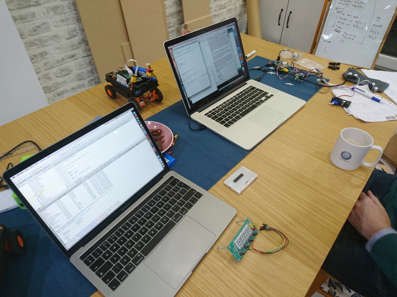
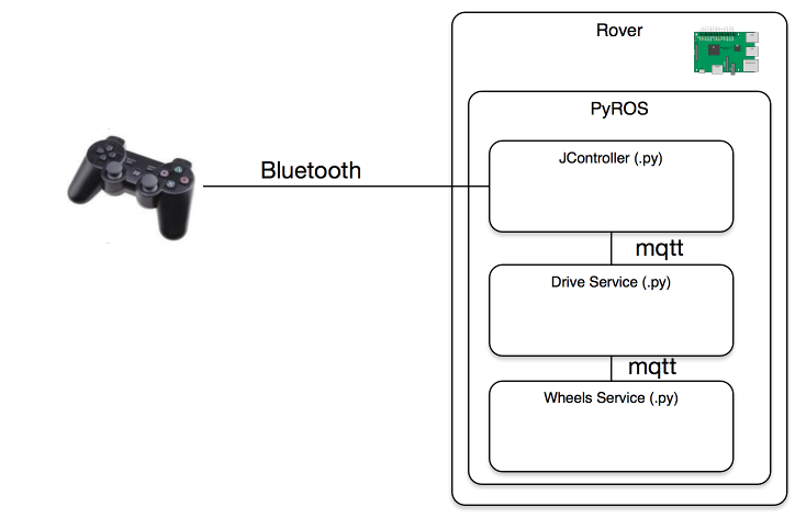
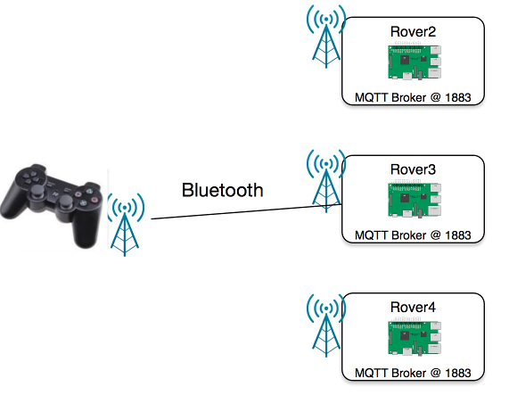 The way we will do this is with a (knockoff) PS3 controller, connected via Bluetooth to the rover. This is way better because there would be far less points in the packets route, and because its more direct, it should have a shorter travel time, meaning less delay. Also, there is no three way acknowledgement TCP robustness relies on. YAY!
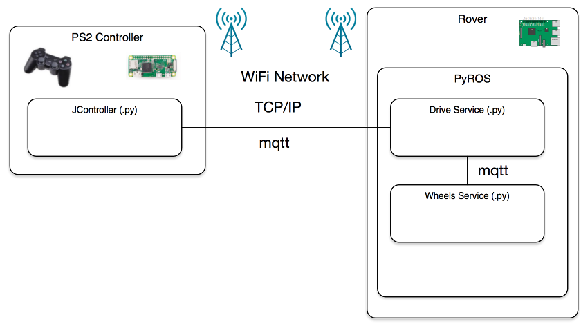
 Guess what we will be doing on our next club meeting on Wednesday! :)
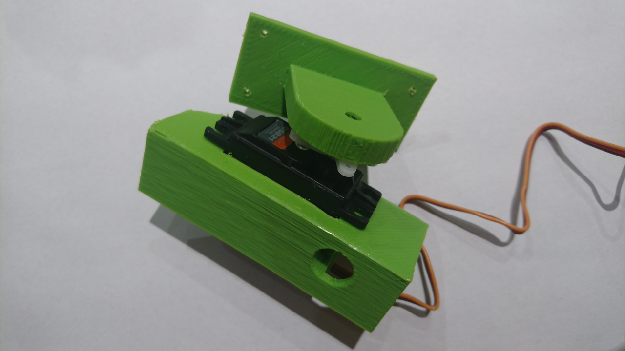
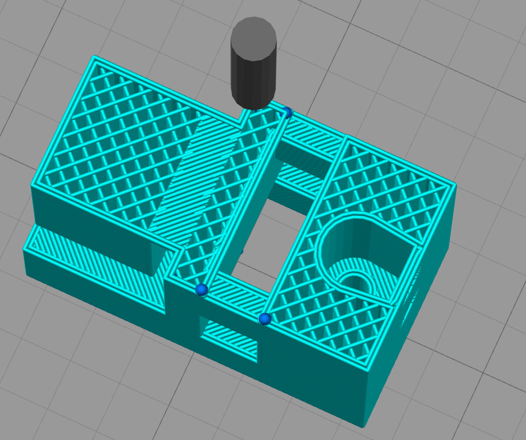
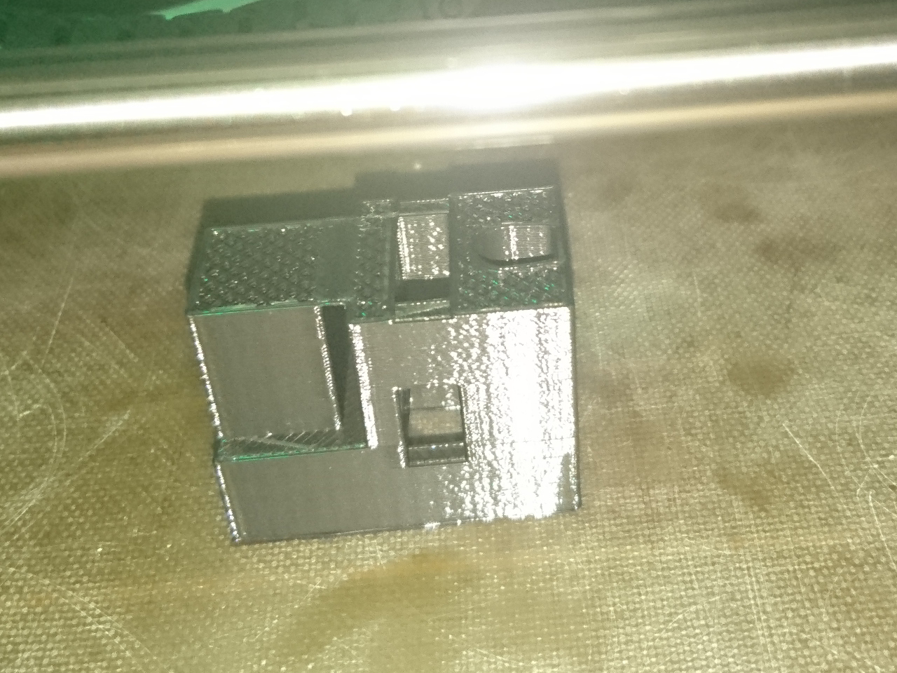
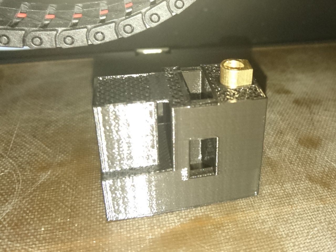
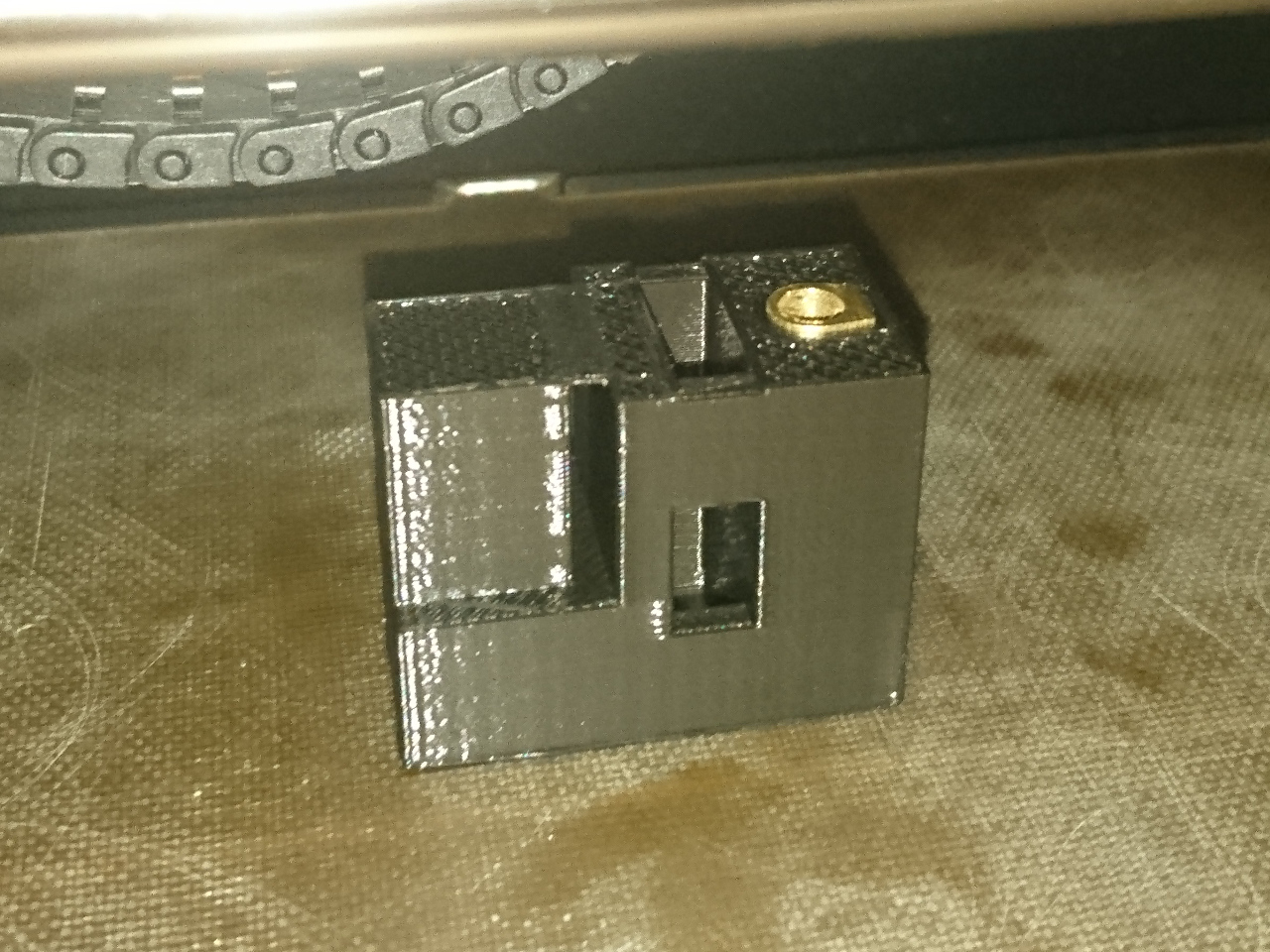
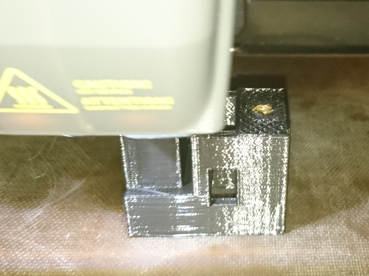
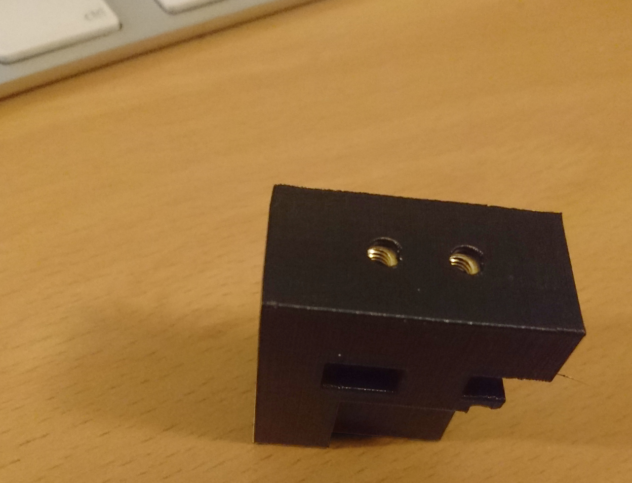
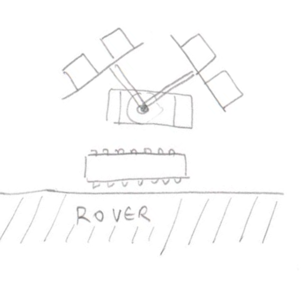
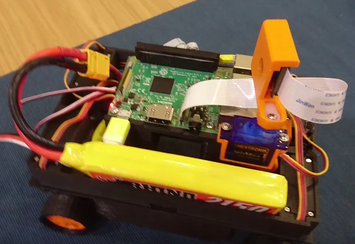
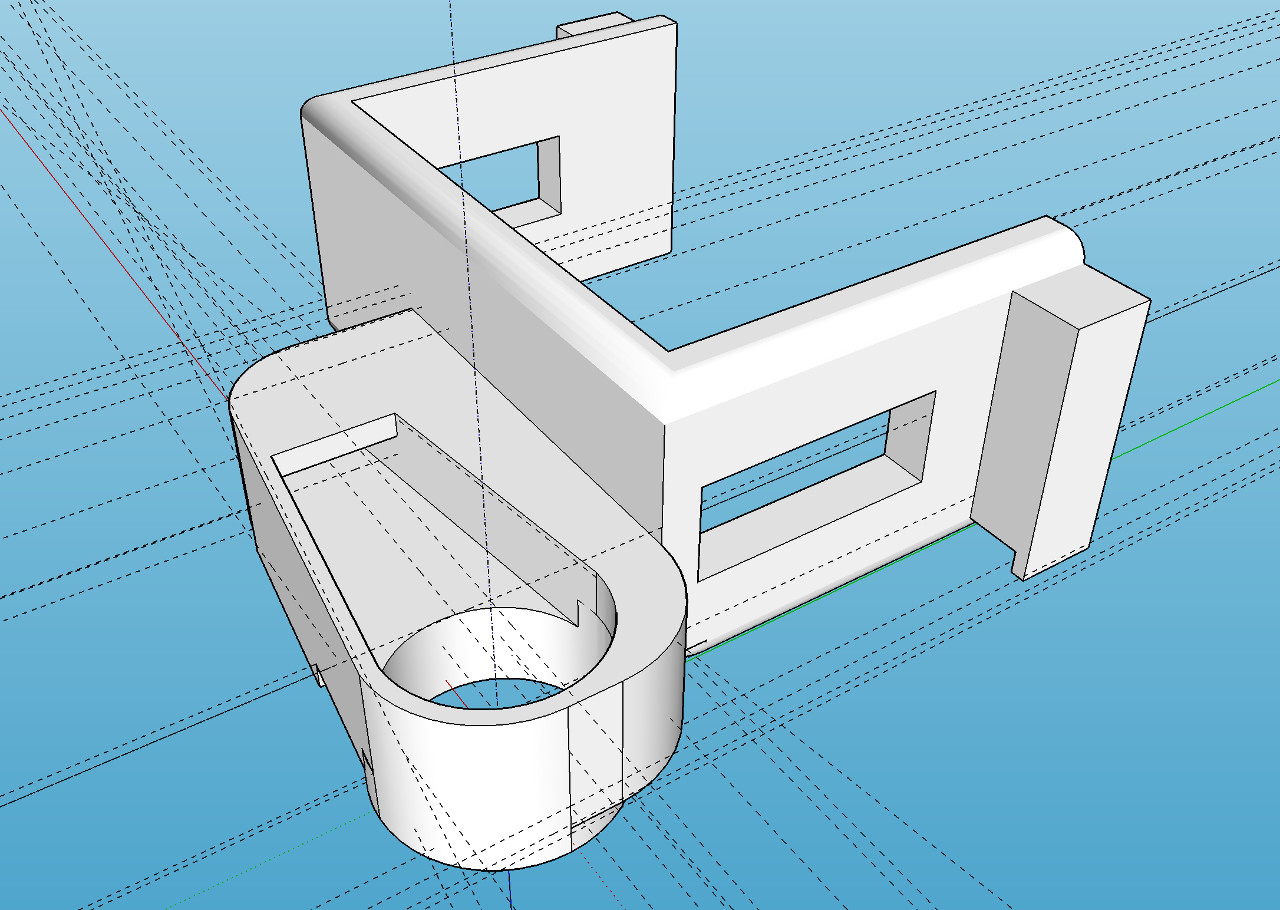 One of such a design decision was the way camera arm is attached to the servos. Idea was that if appropriate retched hole is made, servo shaft would fit and hold. It did to the extend but whole connection was a bit flimsy and would easily slip. Calibrating camera servos and then having the arm slip on the servo shaft would cause even more damage (or add to slipping, rounding the hole even more). The solution for this is to incorporate the original servo arms to the 3D printer parts. The result is here:
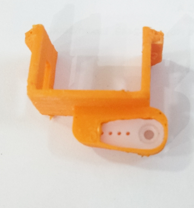
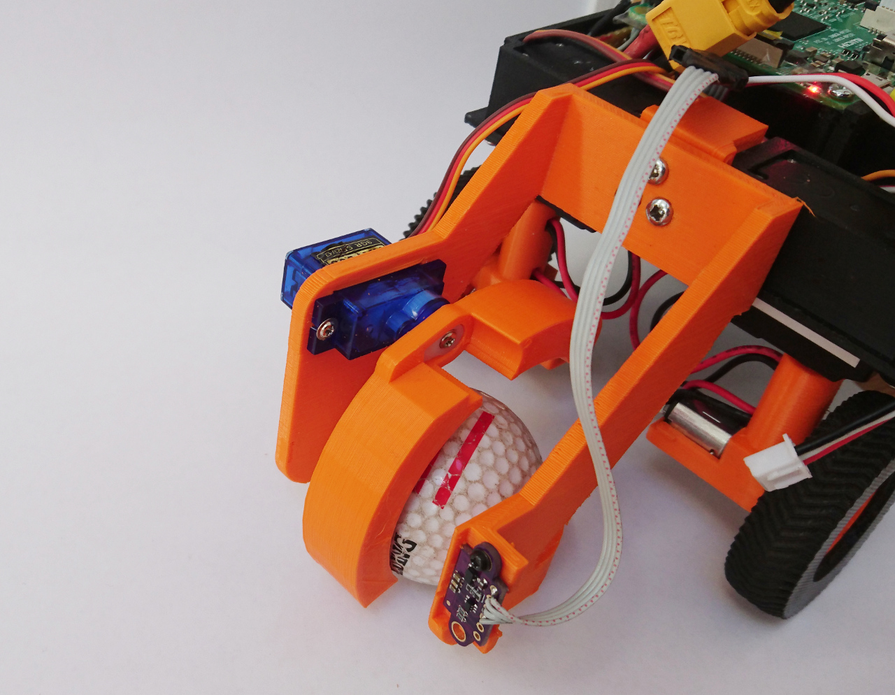
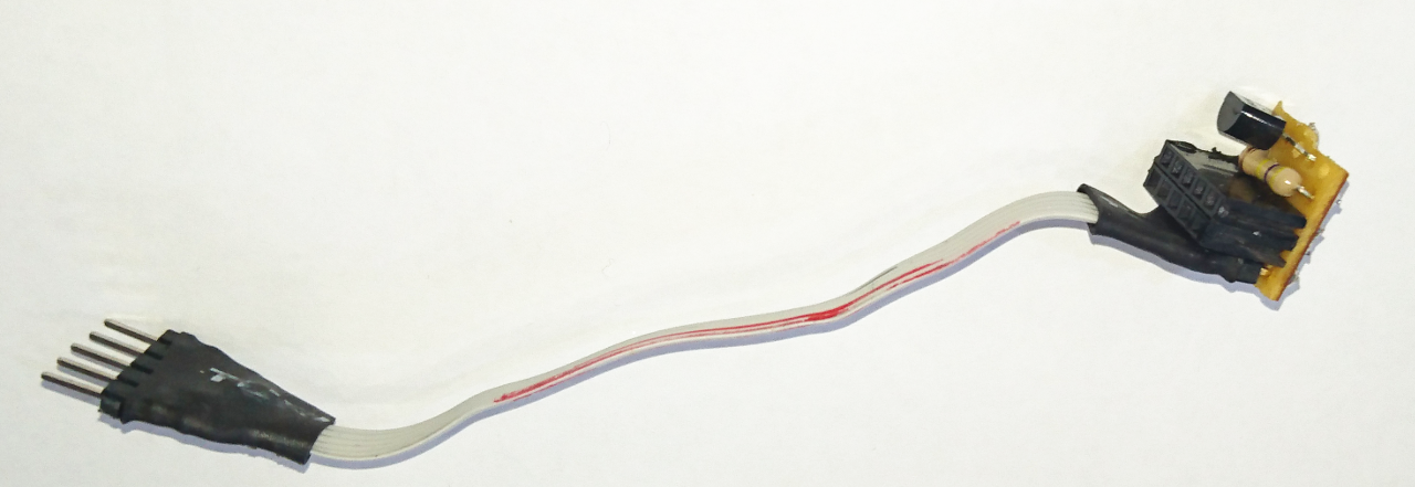
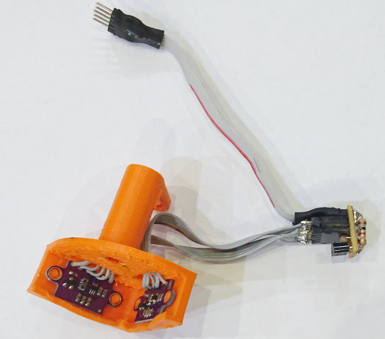
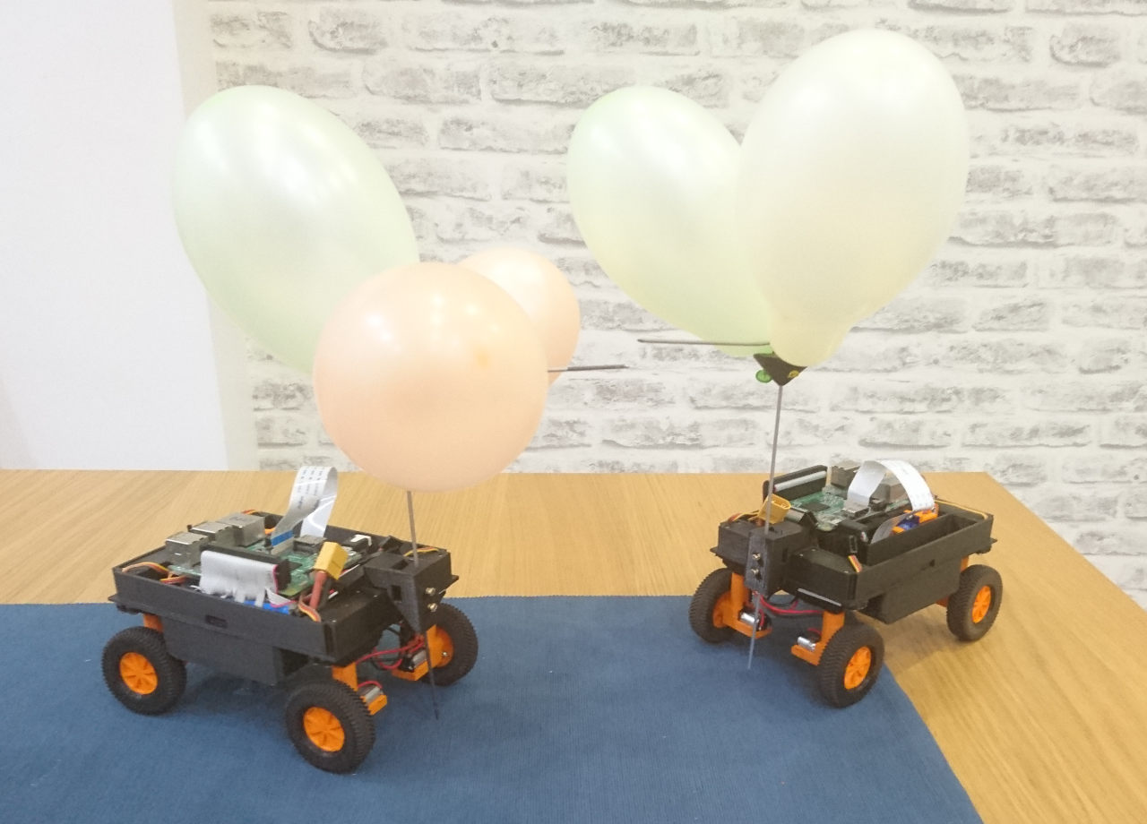
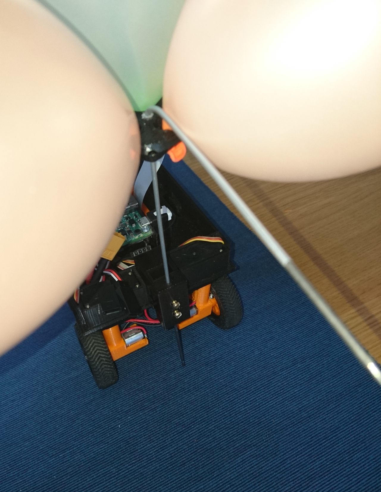
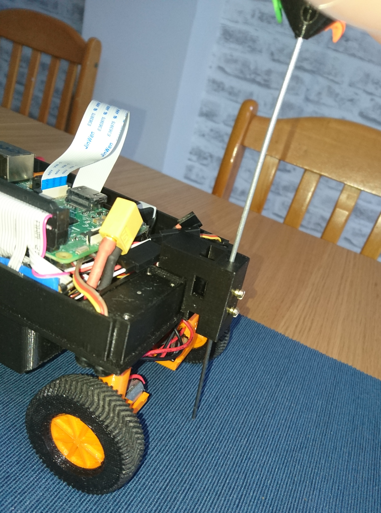
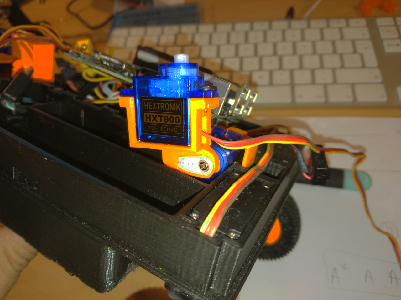 Now we have finally our 'secret' weapon ready to be deployed:
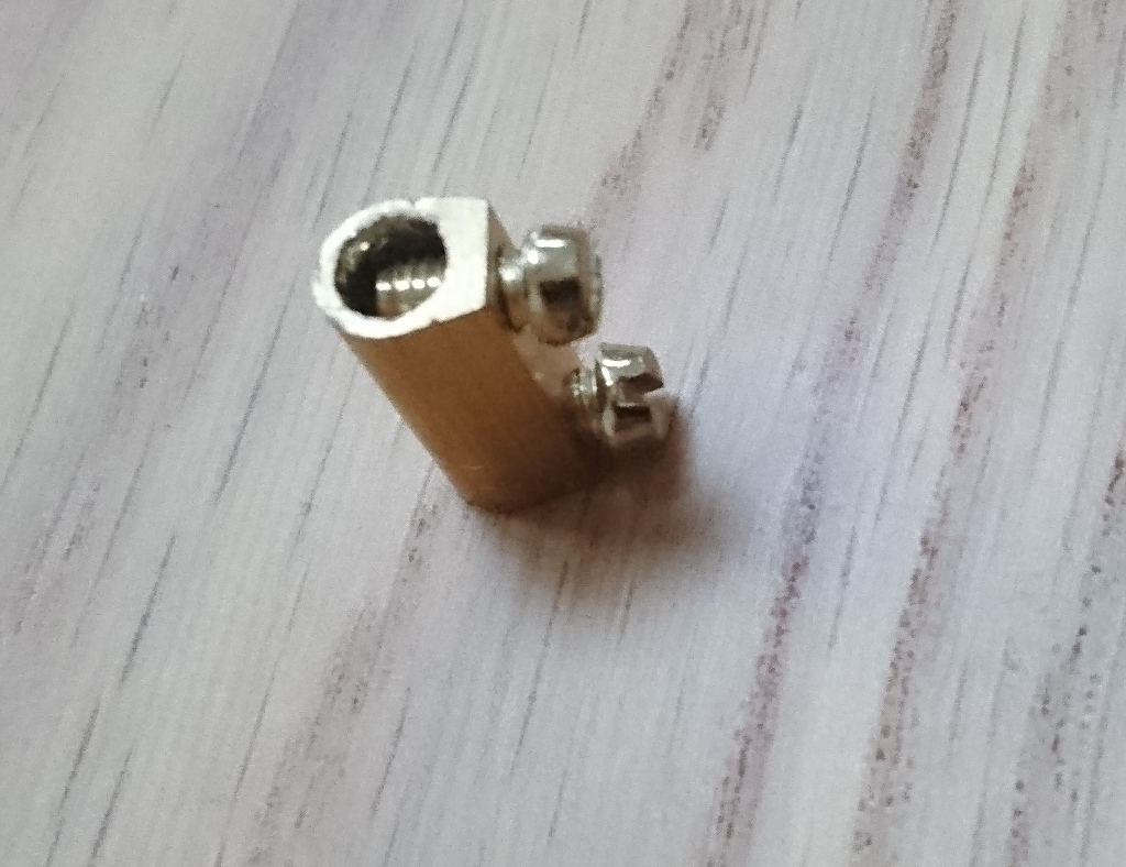
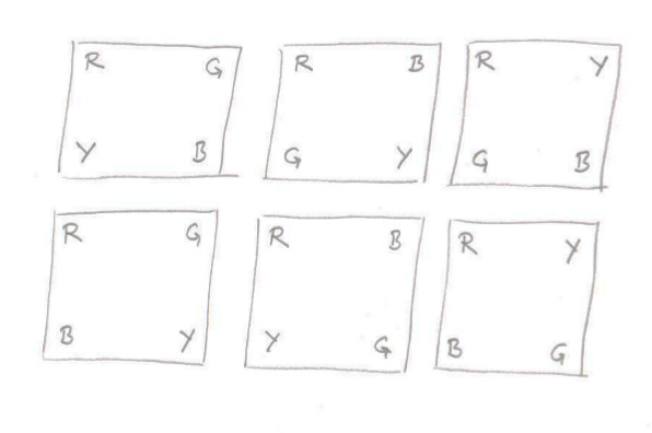
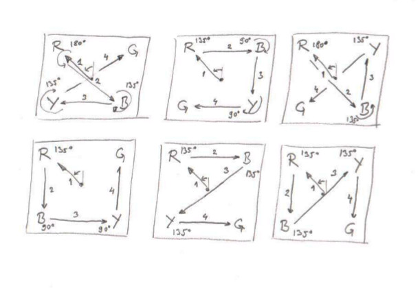
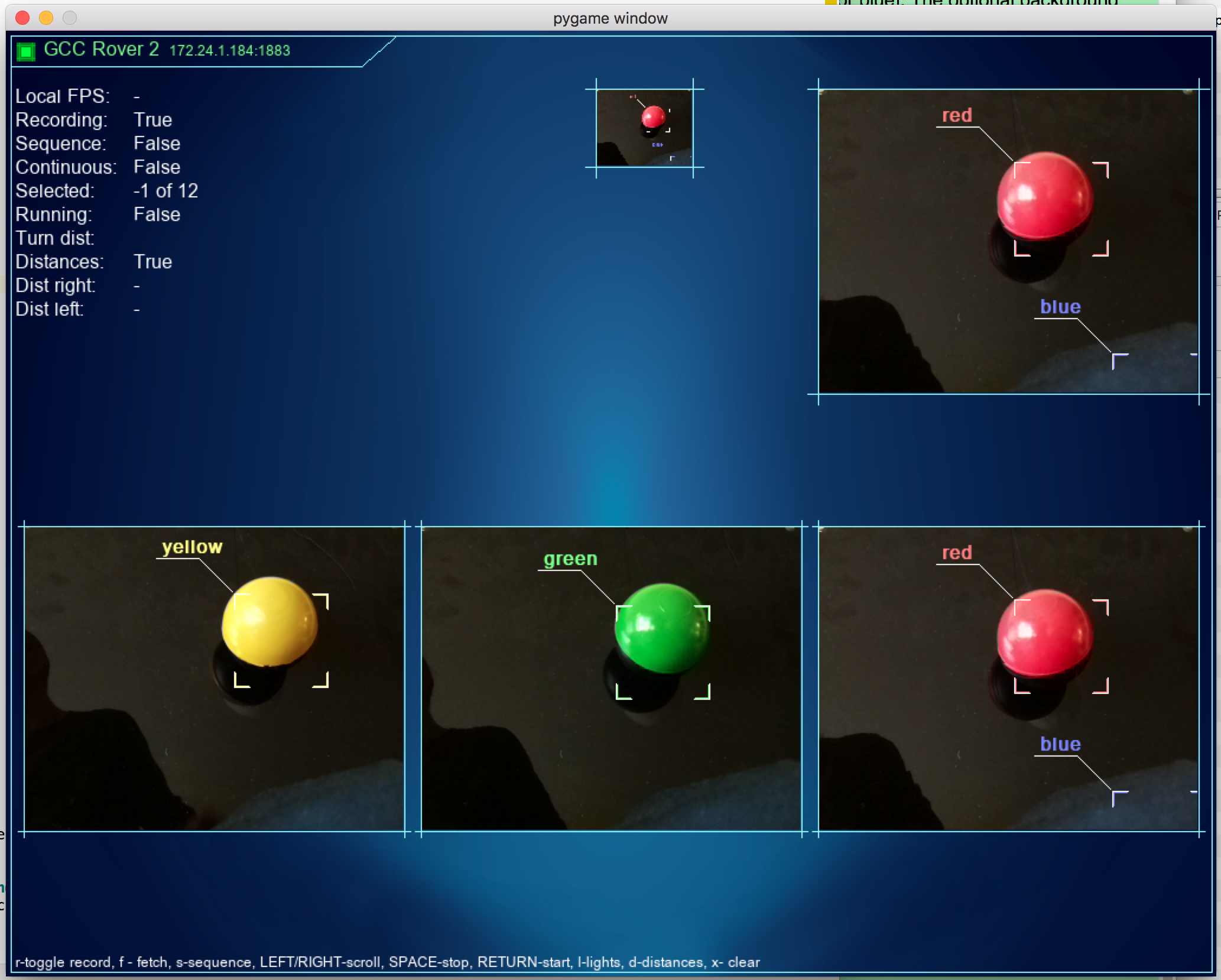
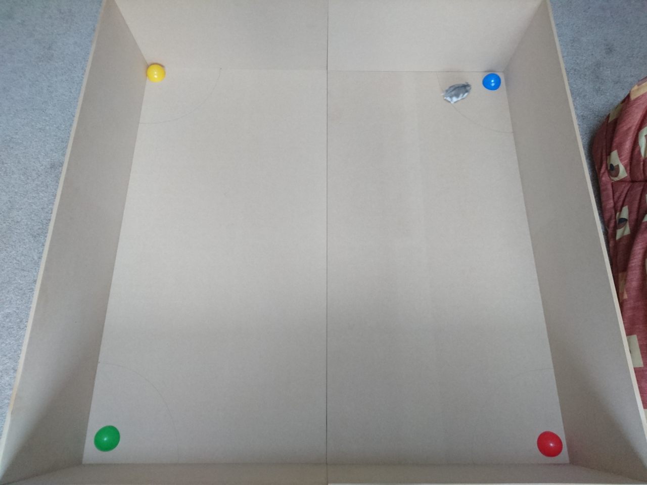
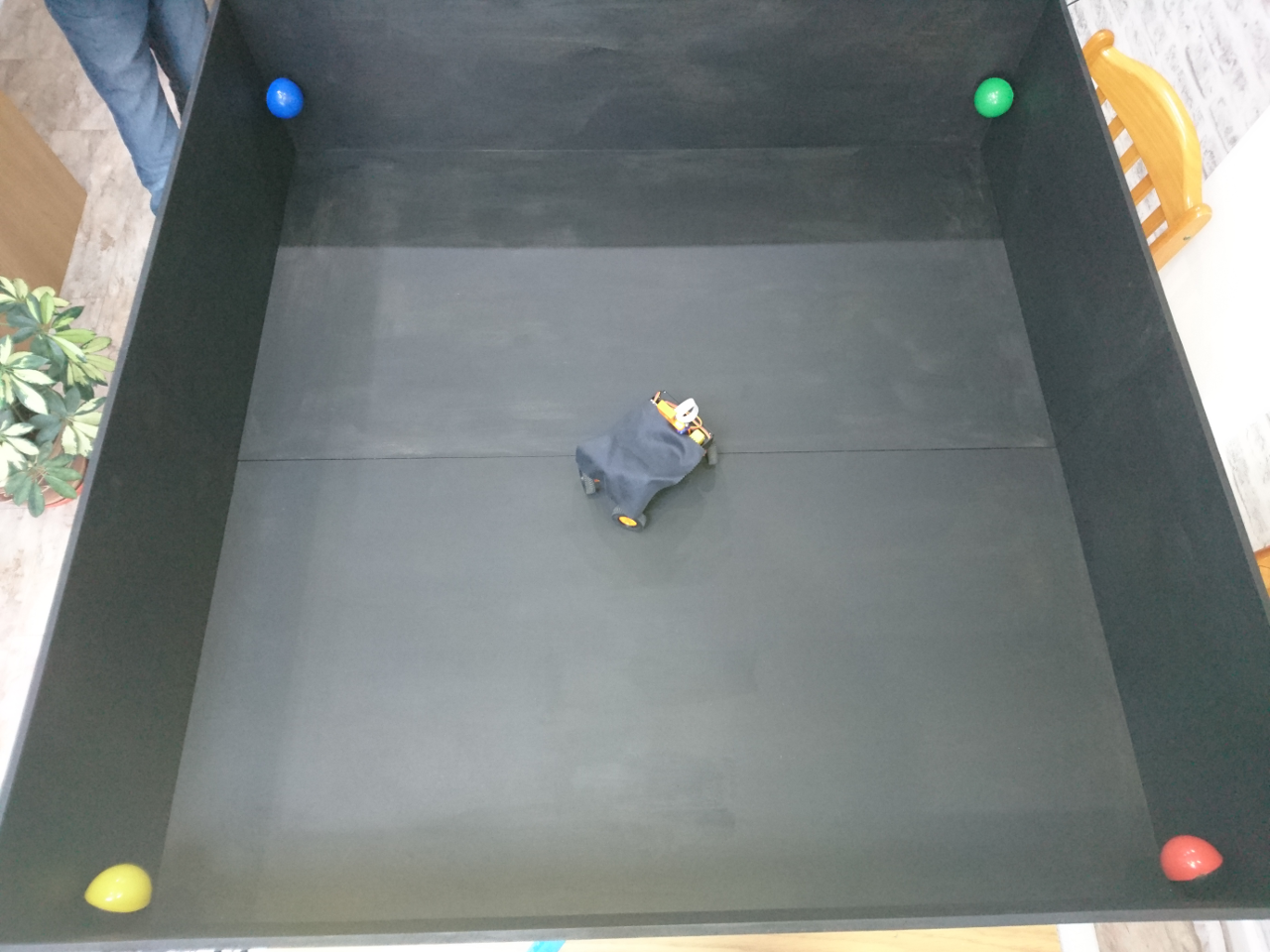
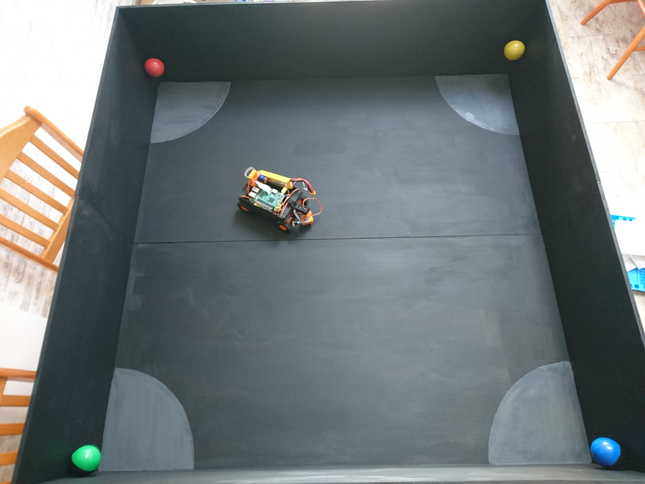
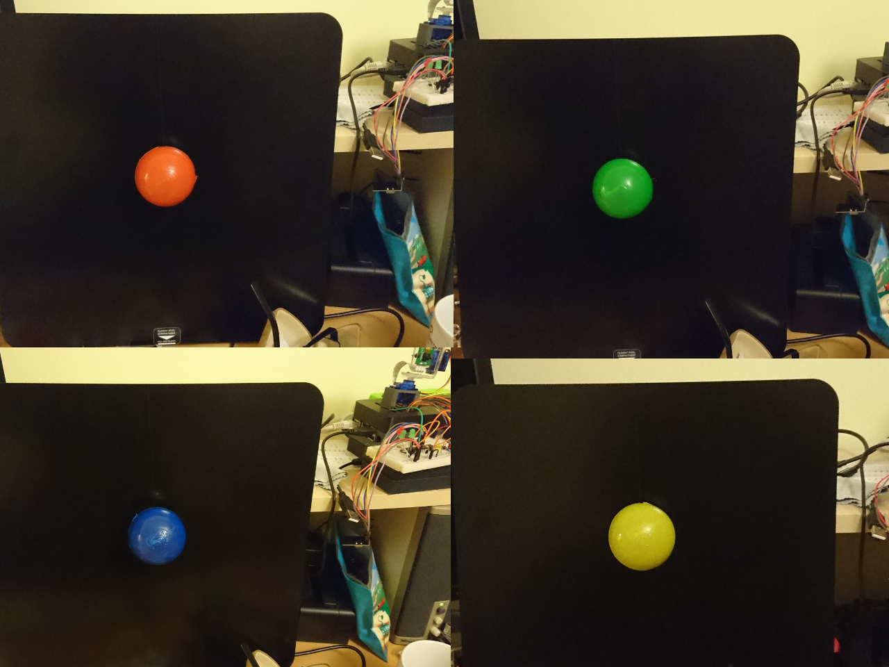
 It was supposed to be used for follow the line (never worked as planned). Our first go will be in adopting existing software which captures images from the camera and scales them to 80x64 pixels and moves them to numpy for processing. The idea is to use as simple code as possible for detecting the presence and position of red, blue, yellow and green on the picture. Also, the code should be as modular as possible so we can, given enough time, later switch to use more advanced software like OpenCV.