Posts about Blog


YGCC Rover


GCC Rover

As this can be last post before the blogging competition is closed let's use this opportunity to describe how far we managed to go with our rover and maybe mention how far more we would like (probably for the next year).

But before that is very important to say that this journey was really interesting and fun. And hard and frustrating at moments. But it was worth it!

GCC Rover M18 aka 'Plan B'

As the 'name' suggests it was mostly composed with 'Plan-B' options and solutions. It really forced us to think on our feed and make hard decisions. At the same time - all those second best options we were forced to pick are really perfect points for improvements, especially now when we have 'working solution'.

First Tier - Wheels
Wheels

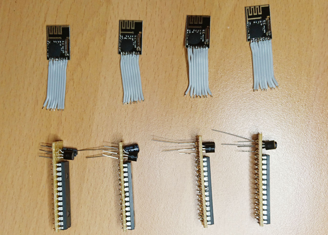
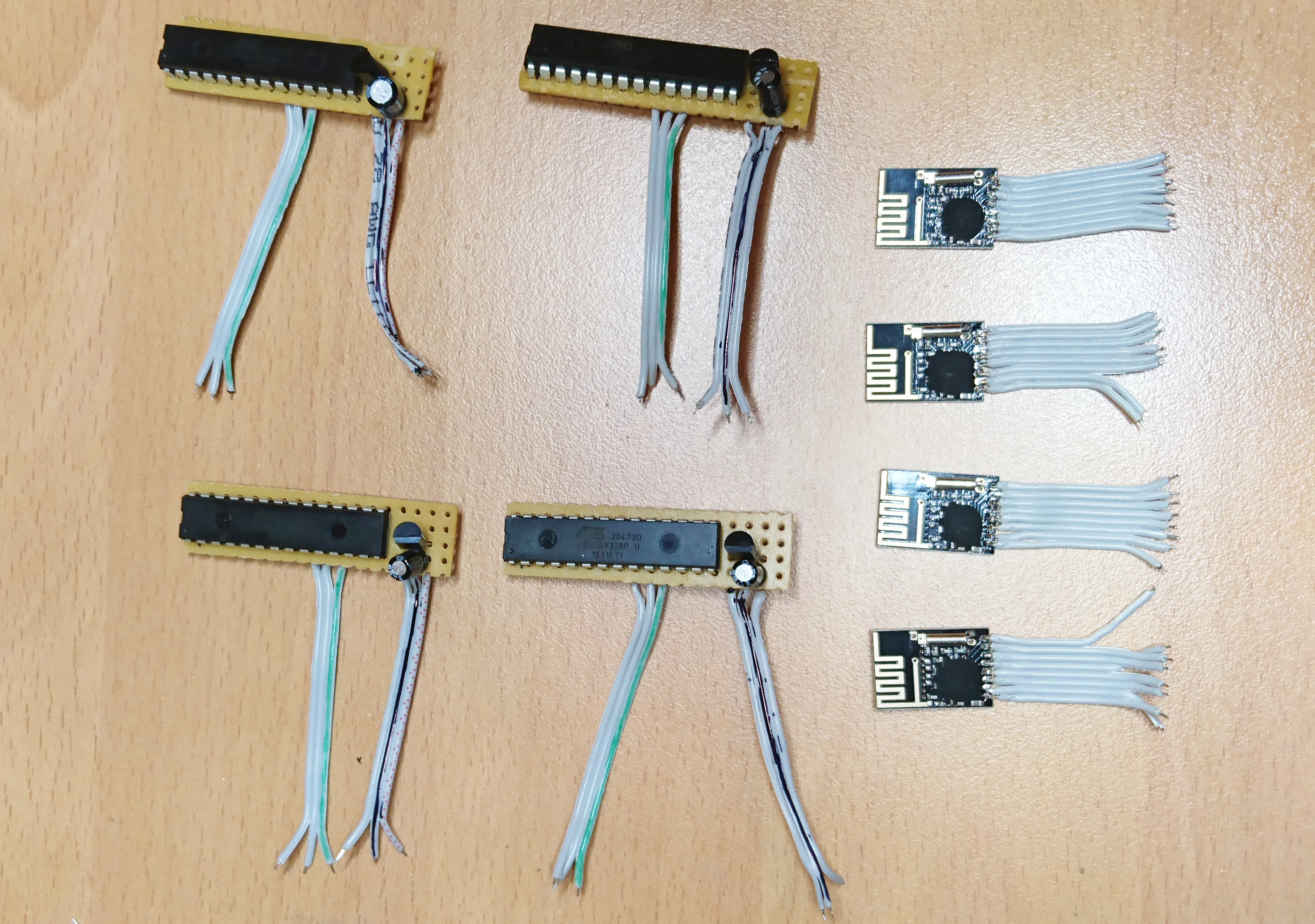
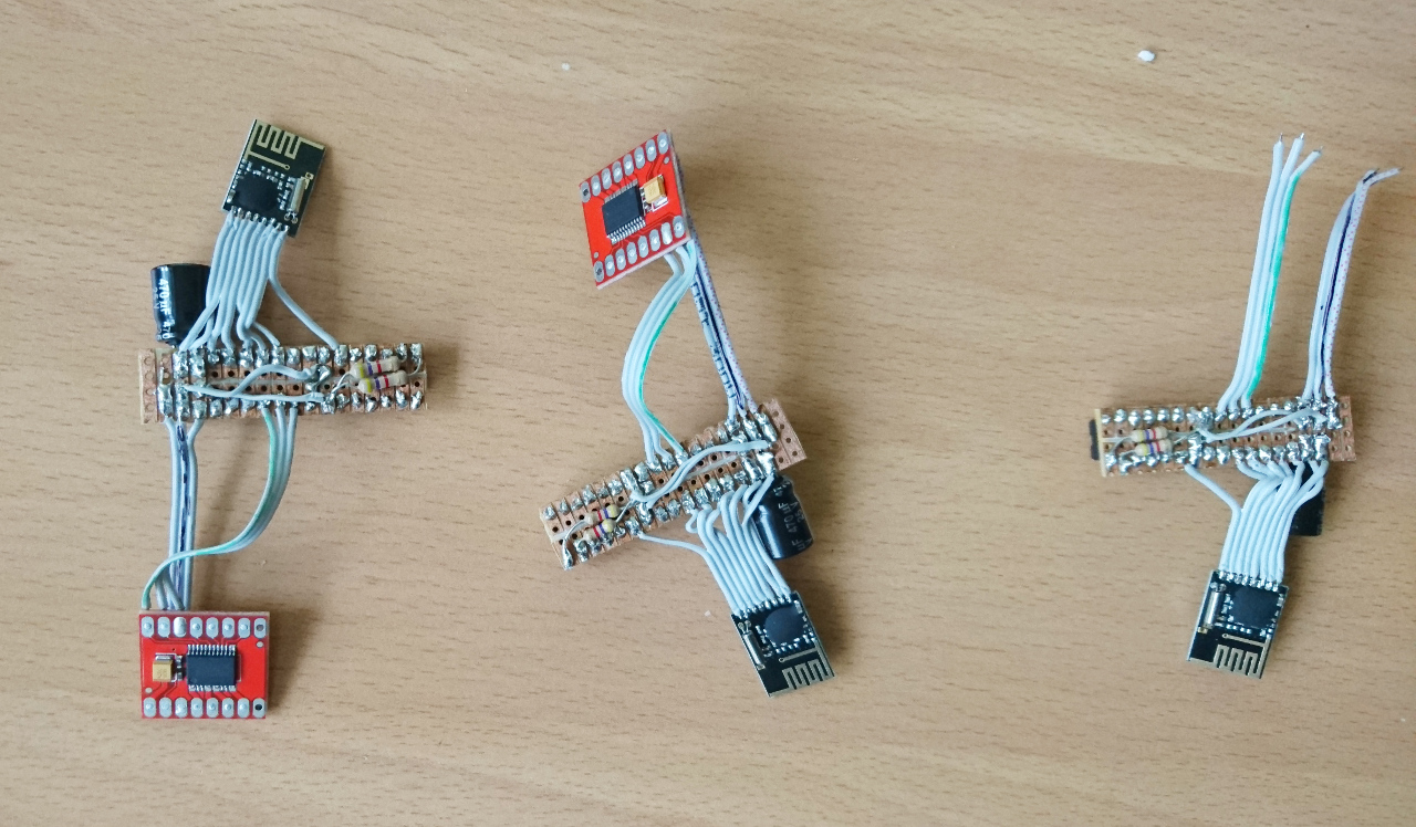
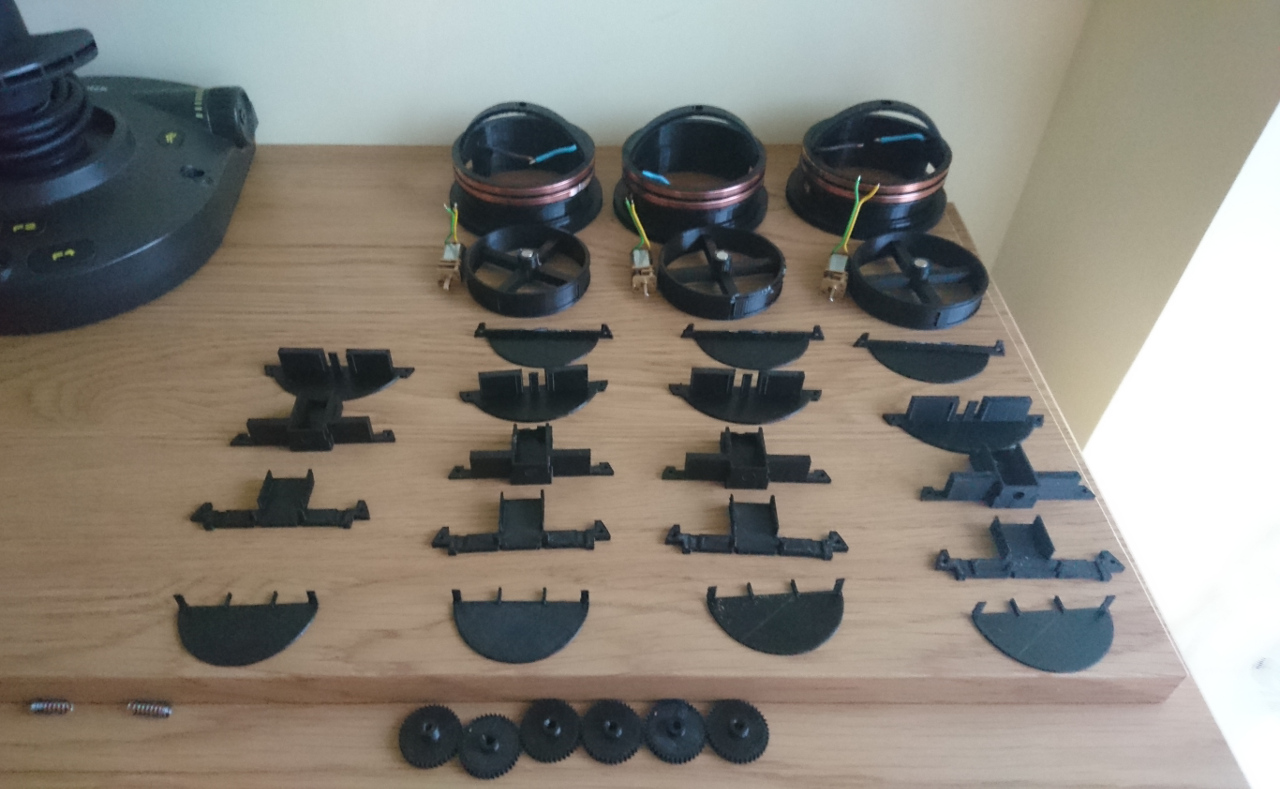
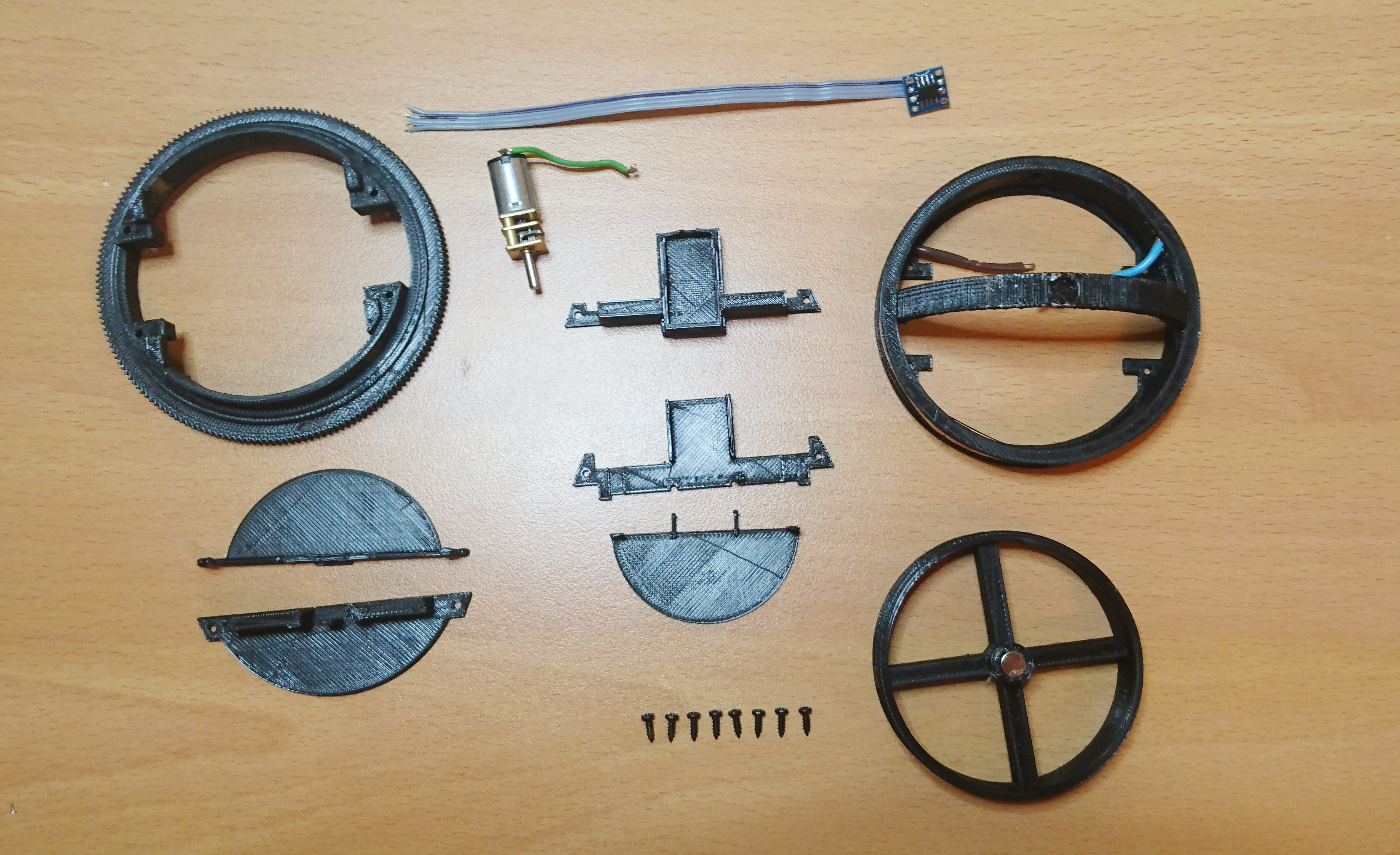
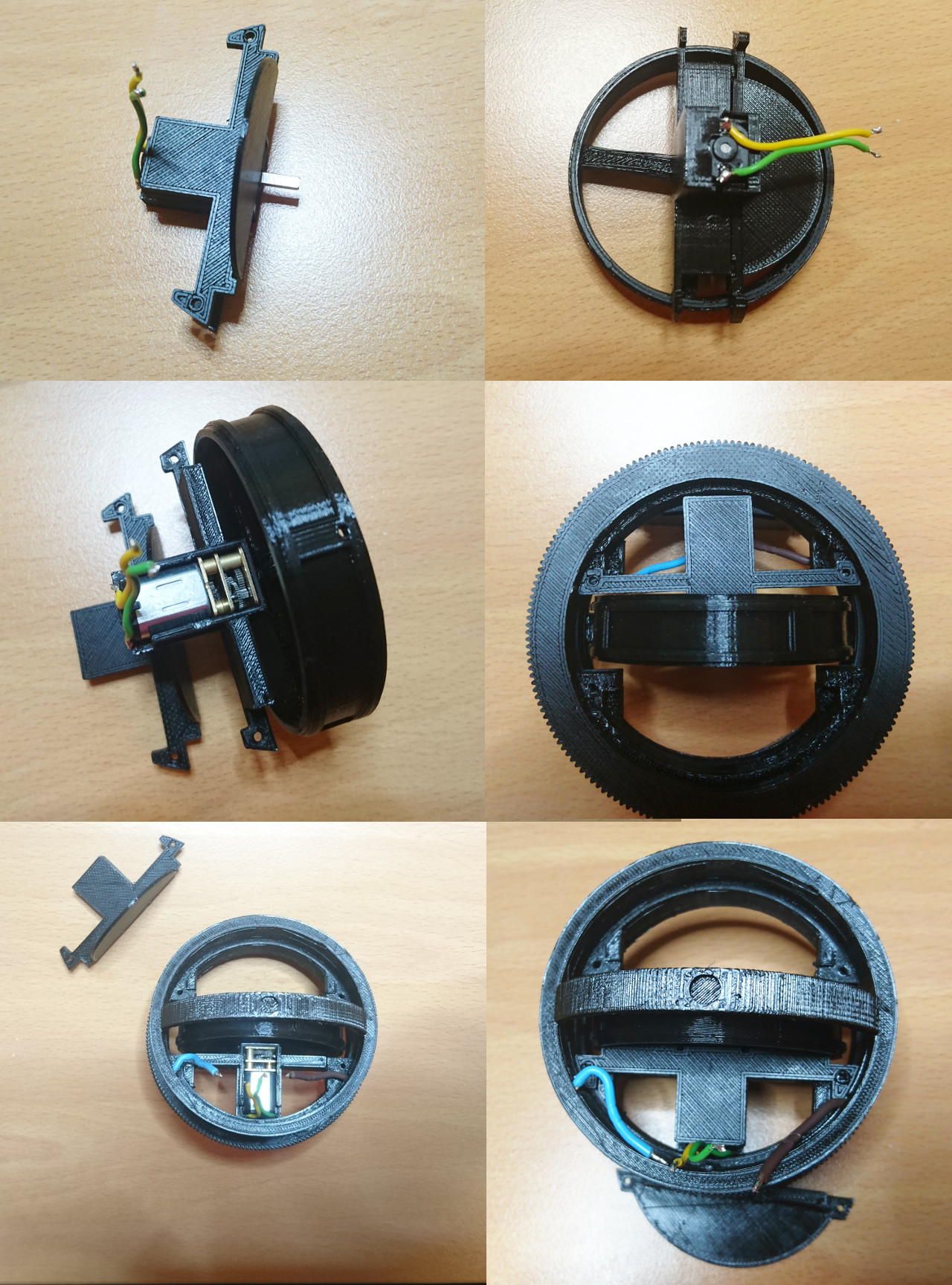
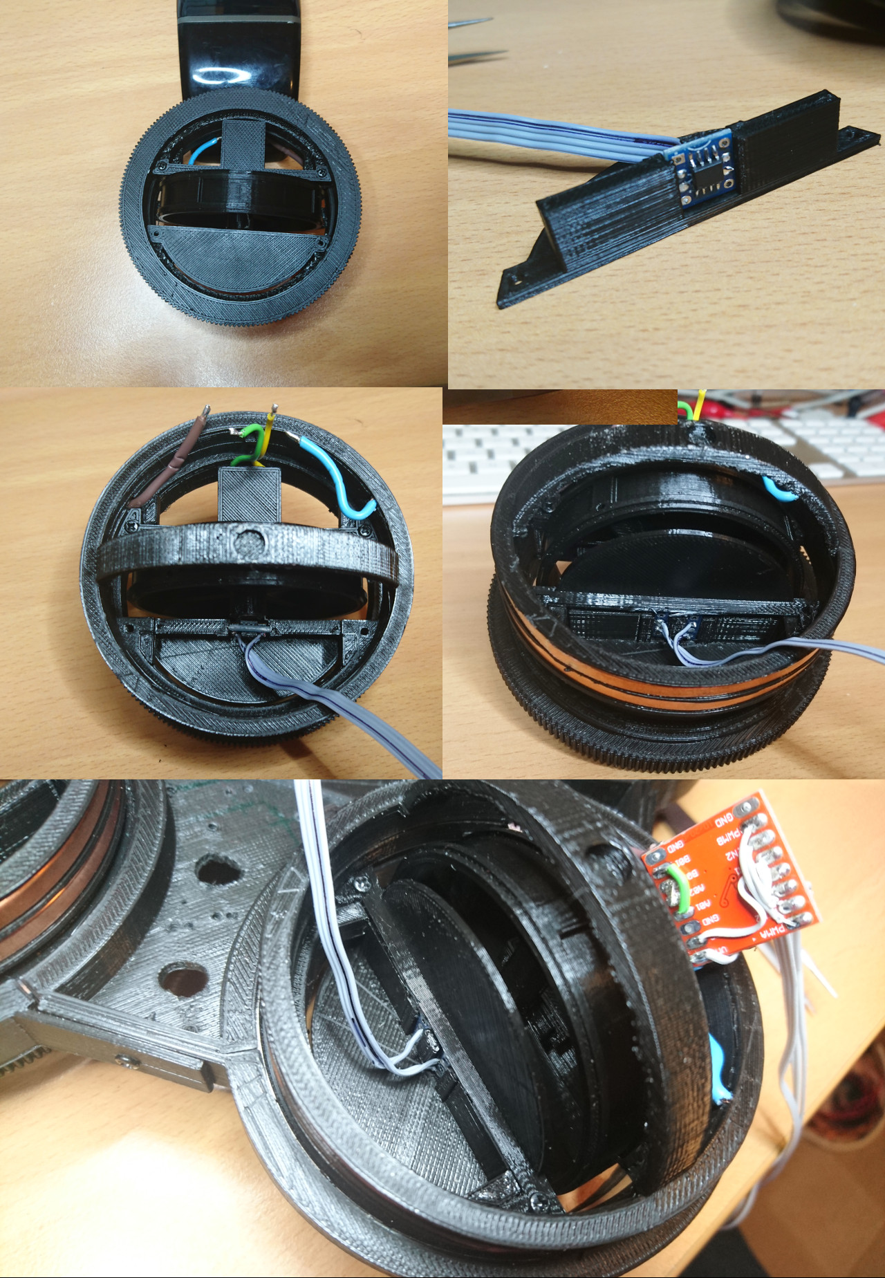
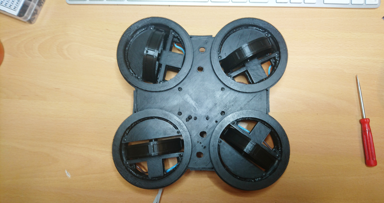
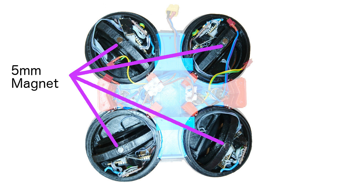
This rover has four wheels where each can rotate 360º. Inside of wheel hubs we have little (dual) H bridge (wired with both sides in parallel) controlled by ATmega328p µController. The same µController reads AS5600 rotational sensor (wheel movement feedback - odometer) and nRF24L01 2.4GHz transceiver to communicate with the main Raspberry Pi. Also, it has 'plan-B' micro geared brushed motor. Motors are geared for 300RPM @ 6V. Wheel hubs house 65mm diameter (~210mm circumference) wheels where last 2mm are printed with ninja-flex flexible material. Our finger in the air check gave result of at least 0.7g for tyre grip. Beside that, each wheel has 5mm magnet in the centre so AS5600 rotational sensor can work.
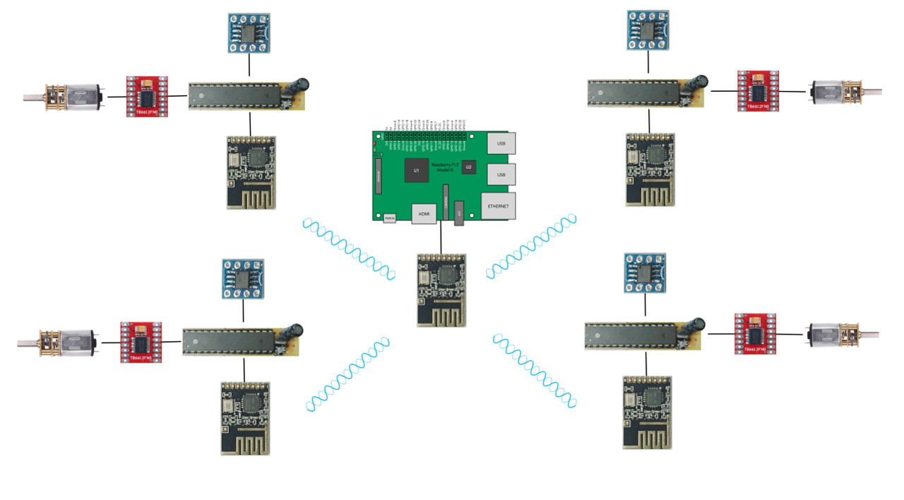
Wheels Wiring

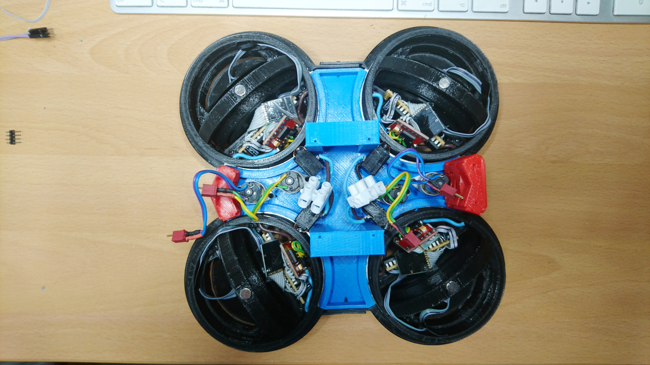
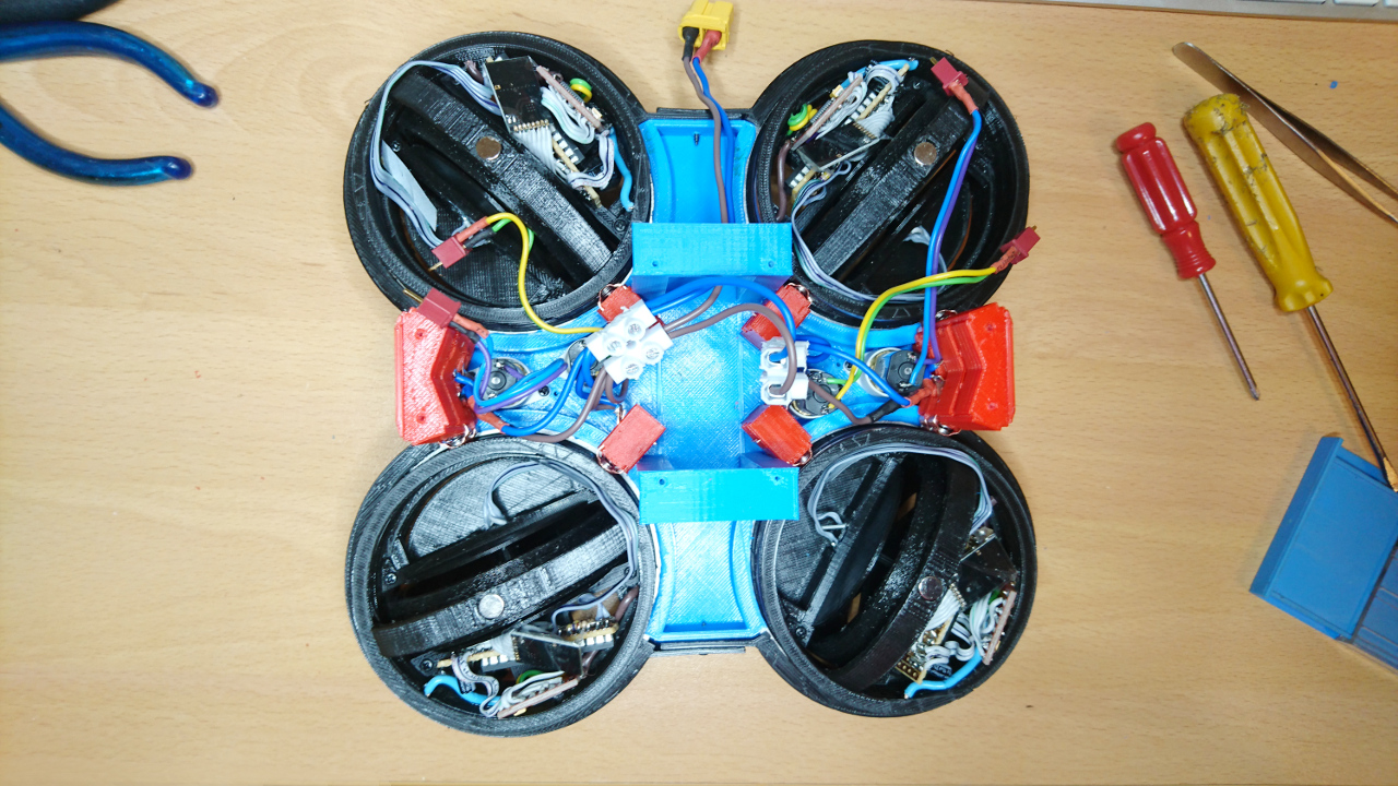
On the outside wheel hubs have copper rings for transferring power to them. Power is transferred by brushes. Each wheel has two set of brushes - just in case that one is not making good contact. This tier is powered through XT60 connector which connect it with the tier above (where battery is connected to).
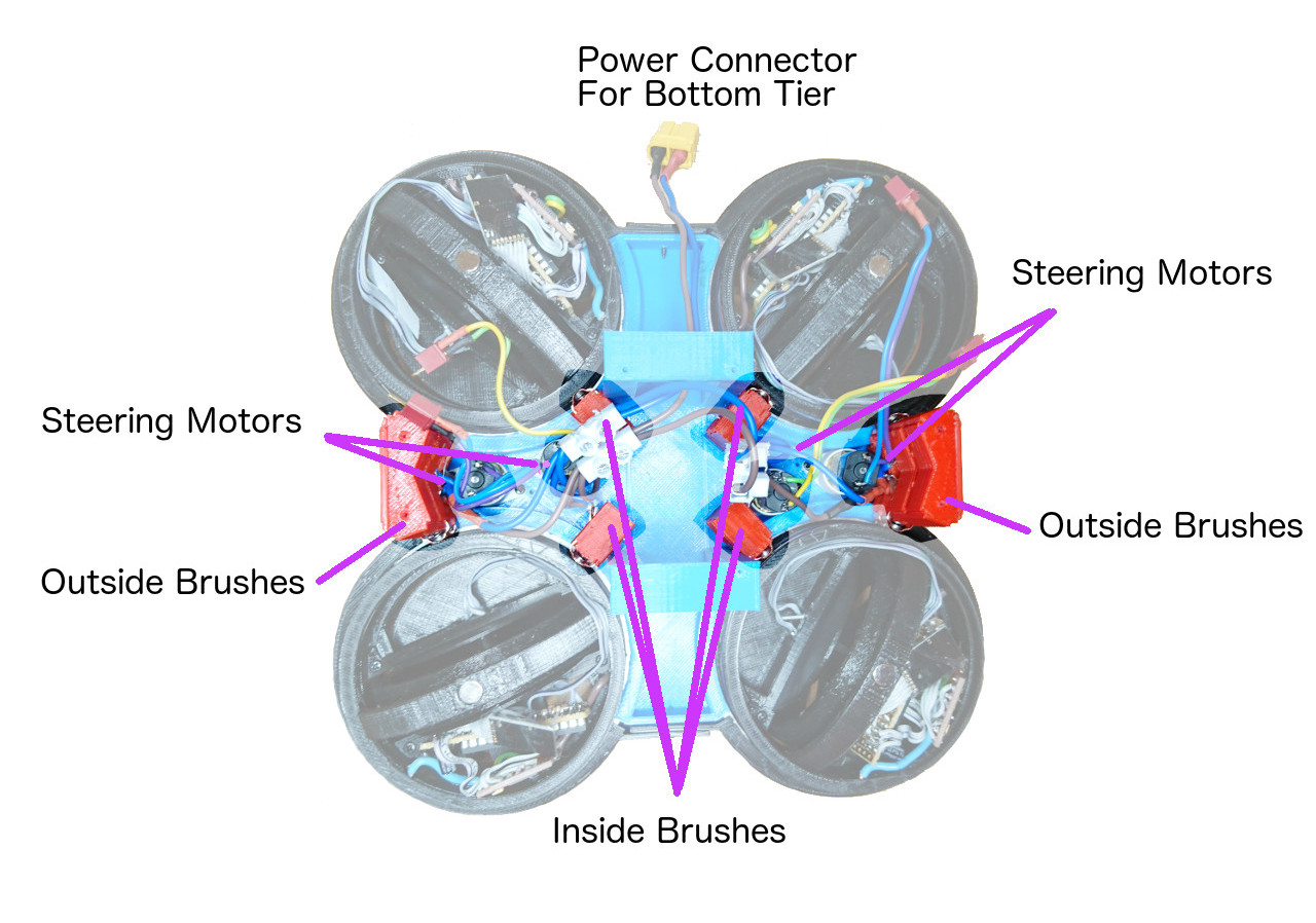
Lower Tier

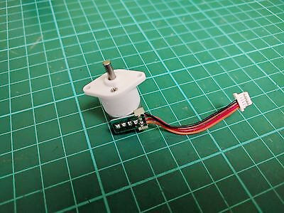
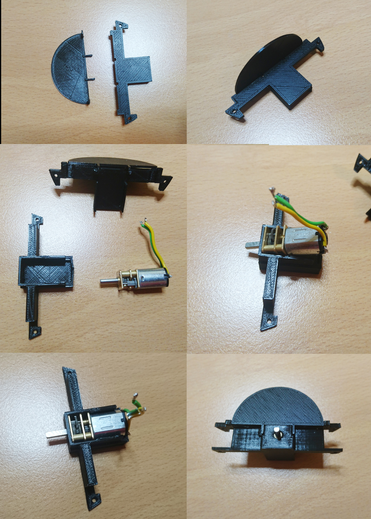
Also, on that level we have 4 little motors (similar, but just geared for 200RPM on 6V). Again, they ended up being 'plan-B' option. Currently they are the fastest that have enough torque to turn wheels. They rotate wheel hubs:
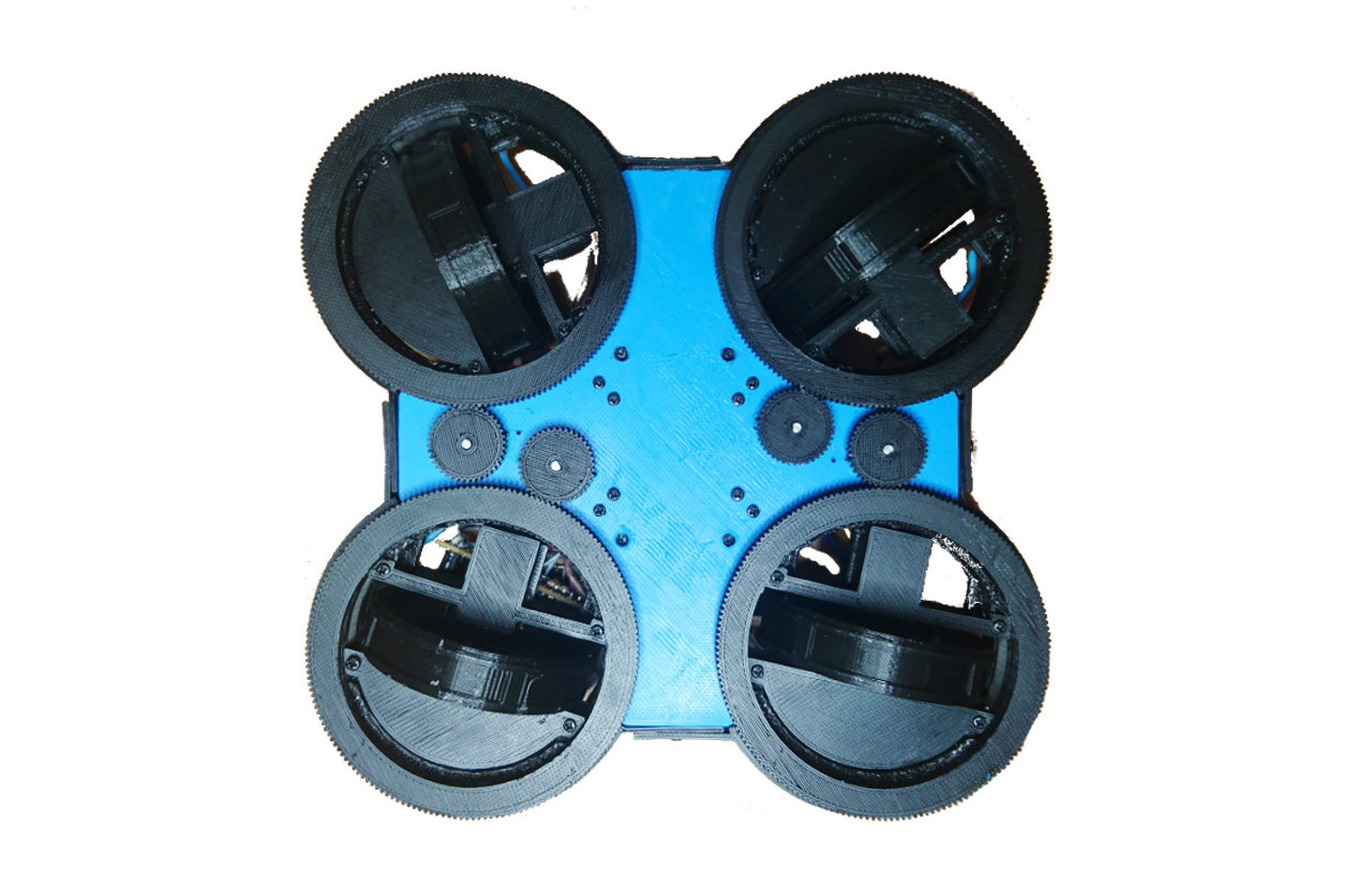
Battery

Their current speed is around 250º/s at the full speed (there is 0.1s or so before they can reach it).

Aside of little motors there is space in the middle of the rover for the LiPo battery:
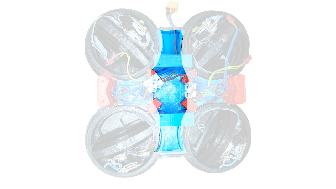
Battery

Middle Tier

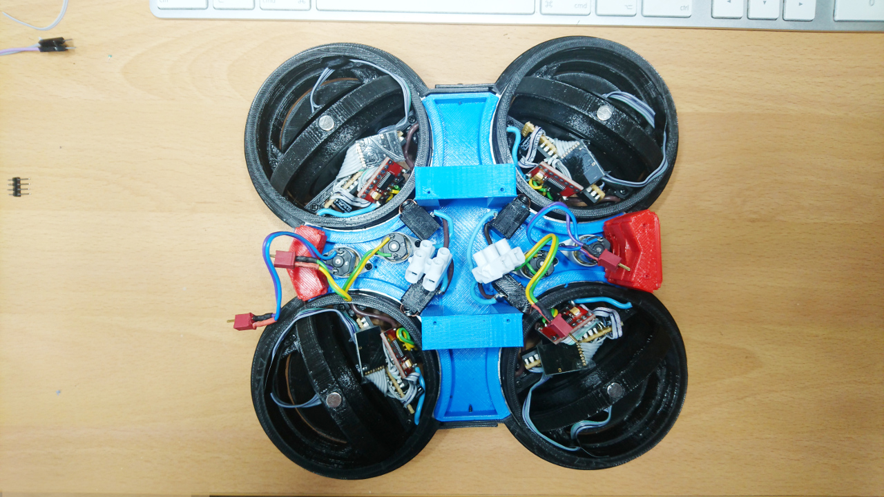
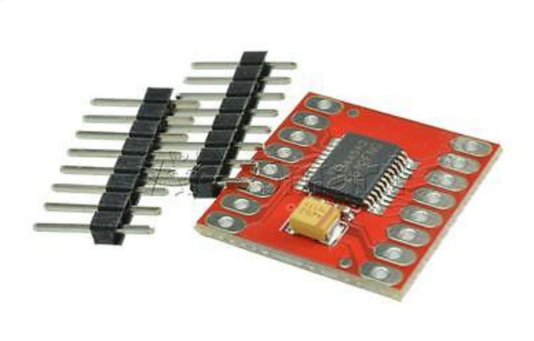
Middle tear has two dual H bridges on the bottom side which are connected with micro deans connectors to steering motors. Also, middle tear plate has hole, just below the main Raspberry Pi, pretty much in the centre of the rover, where the commanding nRF24L01 24.GHz transceiver is mounted.
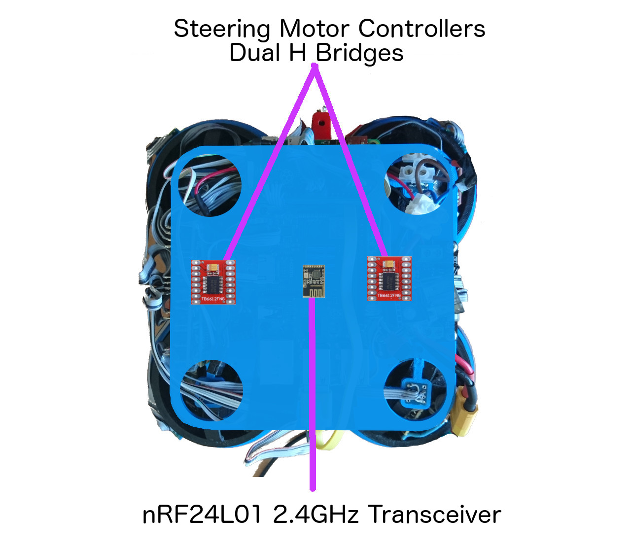
Middle Tier Bottom

The next important thing on that tier are 4 AS5600 rotational sensors, one over each wheel hub. They report back position of each wheel hub. At the top of the wheel hubs are tiny magnets which are read by those sensors.
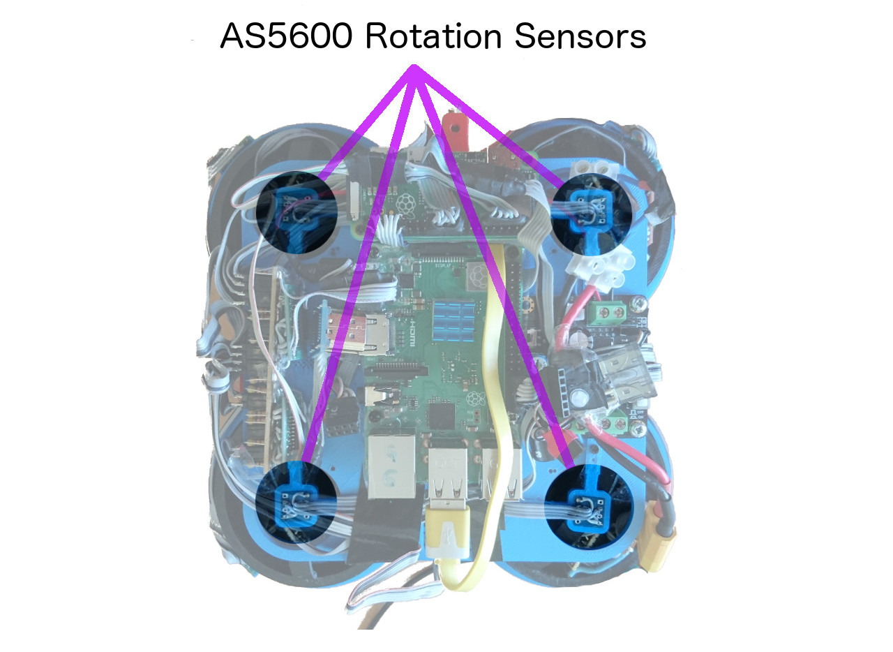
Steering Sensors

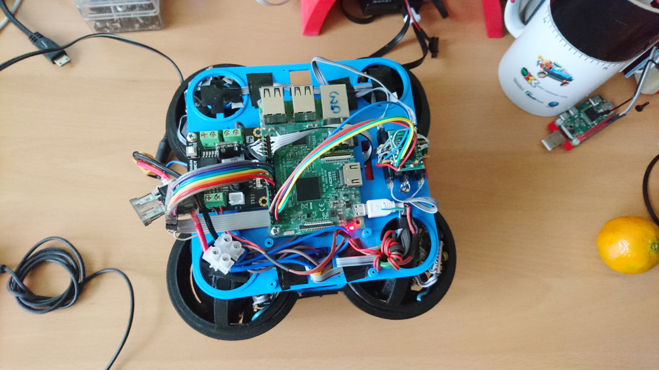
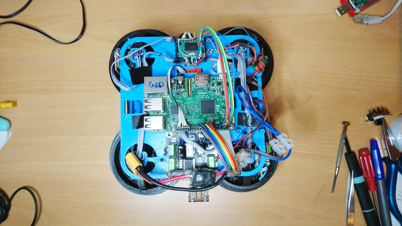
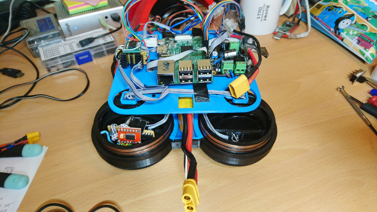
On this tier we have the main Raspberry Pi, 3B+ (with heat sink!) and satellite Raspberry Pi Zero which is charge of steering wheels and communicating with µControllers in side of wheel hubs. Next to them is DC-2-DC power supply of stable 5V for Raspberry Pies and other sensors and a board for various i²c devices (as explained here and here). Main Raspberry Pi and Pi Zero are connected through USB cable.
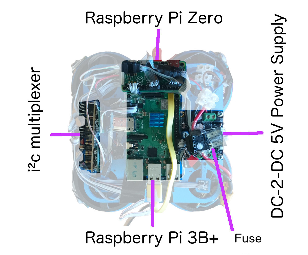
Middle Tier Top

Top Tier

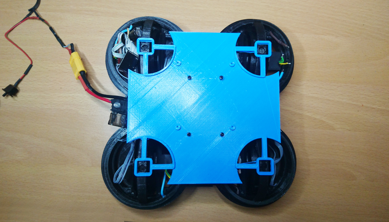
Here we have top plate which, on the inner side, holds 9 degrees of freedom sensor, Adafruit's sensor (gyroscope, accelerometer and compass); little mono amplifier and a speaker. Also, we can say that 3.5" touch screen with resolution of 320x480 belongs to this tier, too. Top plate, also, has two slots for 'attachments' and 8 slots (at 45º apart) for Raspberry Pi cameras.
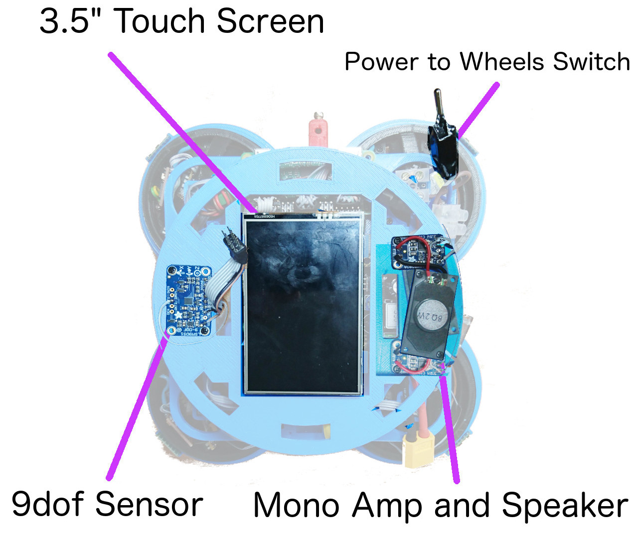
Top

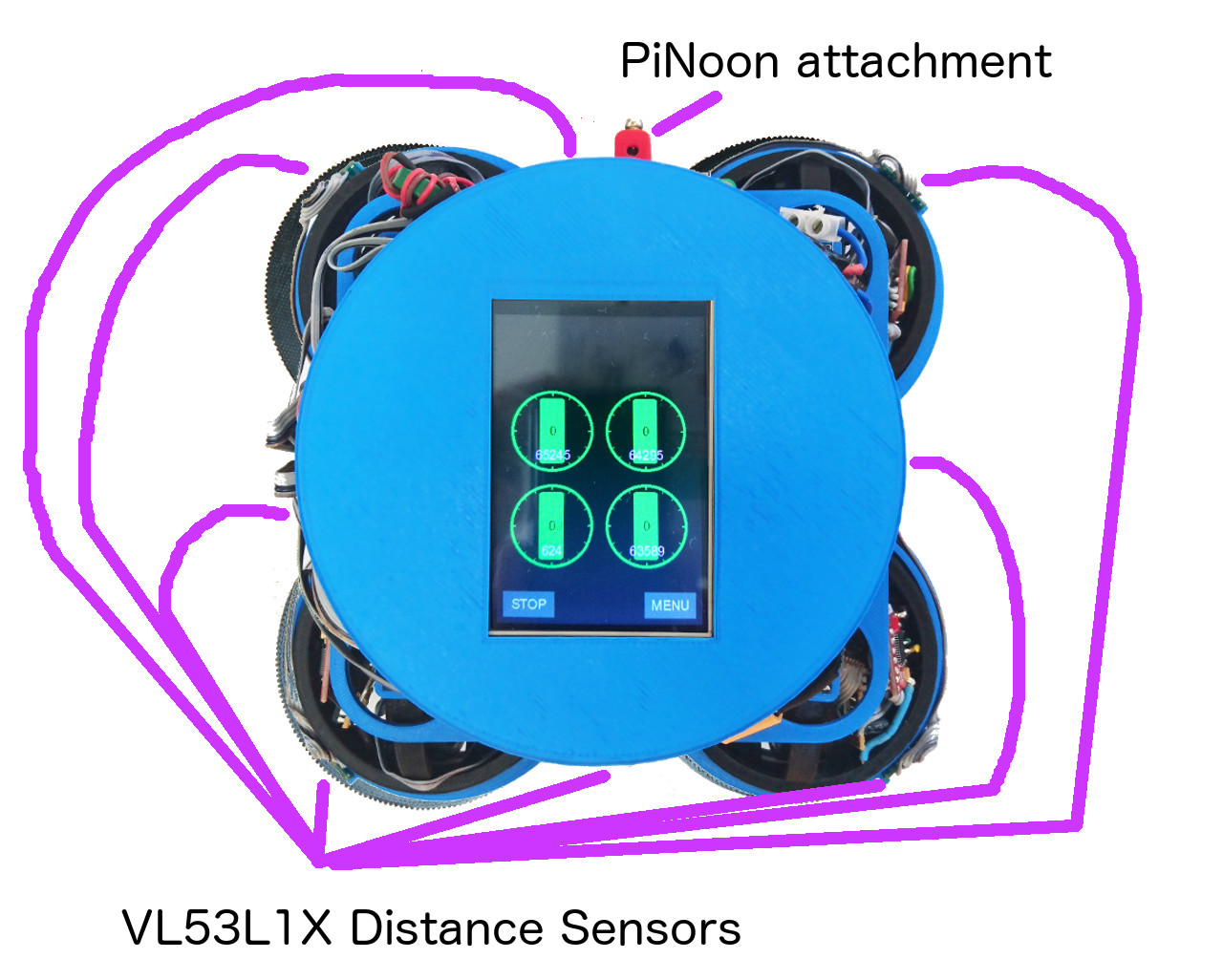
Worth mentioning are VL53L1X time of flight distance sensors that are, really, mounted on four 'corners' at the bearings wheel hub levels and four recesses (not really visible on the picture). They provide 360º distances information at each 45º.

Also, at the 'front' we have place for PiNoon and Spirit of Curiosity challenges attachments.
Top

Bottom And Stand

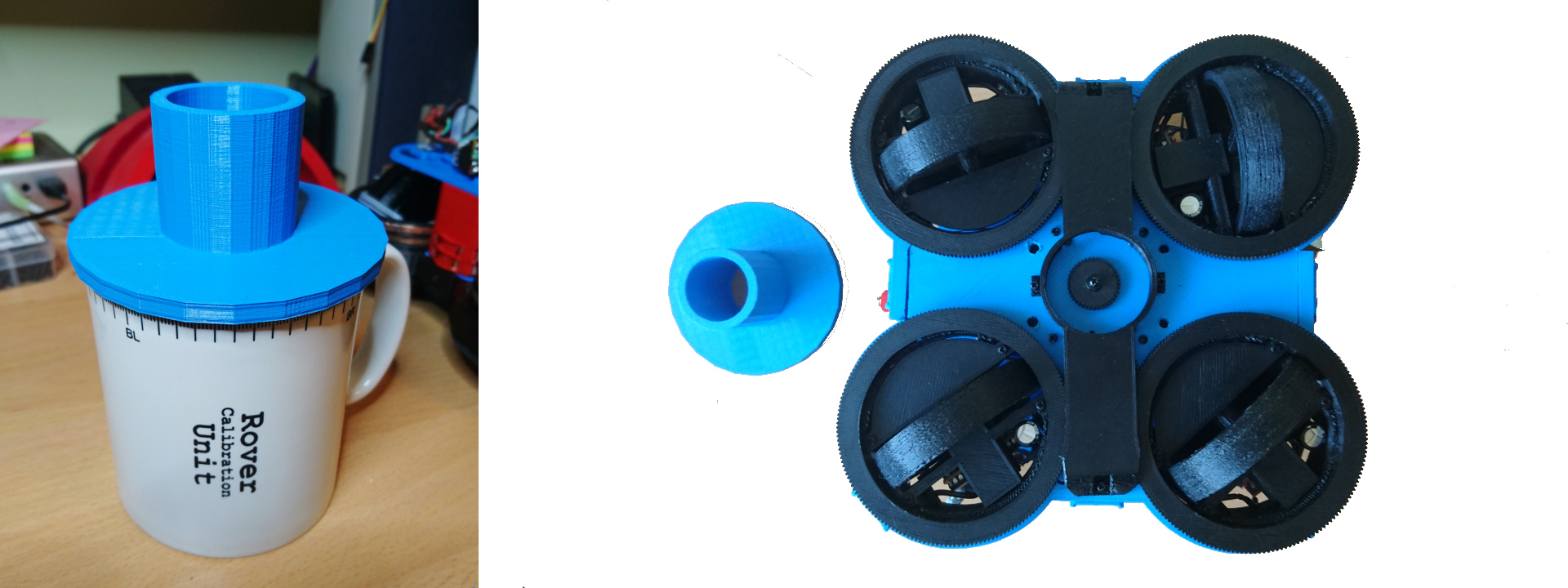
Since we've been through all the hardware of our rover it would be shame not to mention something that's not strictly on the rover but has been extensively used while working on the rover: the stand. THat tiny piece of 3D plastic was one of the best things we've done in last three years of PiWars engagements. It allowed easy access to all sides of the rover letting it freely spin around Z axis while keeping wheels off the ground and without any obstructions.
Rover Stand

Aside that you can see very thin gears guard, too, which, at the same time serves as a guide for the stand. Tiny gear in the middle has its own mysteries. It is there for...

Software

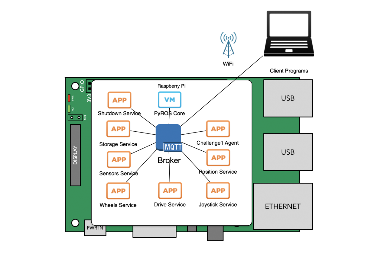
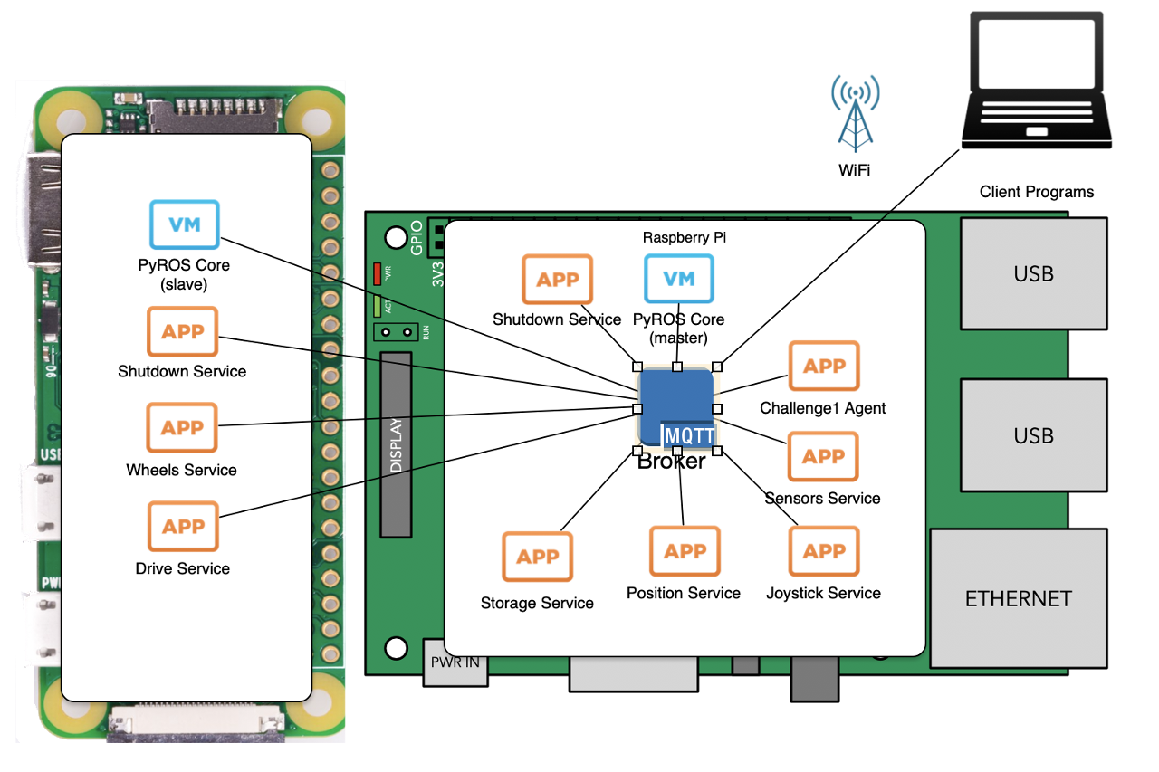
As mentioned many times our rover is 'powered' by PyROS (Python Rover Operating System) - a python service started by systemd unix service, which, in turn, provides interconnectivity between PyROS programs, agents and services (simple Python programs which can use pyroslib). PyROS services are started at the start up of the PyROS, while agents are sent by client programs (usually running at our laptops) to be execute don the rover for particular challenge. We've already written a lot about PyROS and quite a few aspects of it.

Currently our rover on main Raspberry Pi runs following services:

  • discovery service - allows our rover so be seen by pyros command line tools and client programs
  • shutdown service - shuts down Raspberry Pi on demand. It can be triggered by MQTT message through client app, touch screen, pyros command line tool. This service will issue MQTT message for satellite Pi(s) to shutdown and wait for usb(x) (usb0, usb1, ...) network interfaces to disappear denoting that those satellite pies have shut down and only then progress with shutdown of the main Raspberry Pi.
  • wifi service - allows easy set of wpa_supplicant WiFi networks
  • storage service - similar to windows registry - stores key/value pairs to a file (persists them) and reads them back over MQTT on demand. Also keys are in a form of paths. Wheel calibration details are, for instance, stored through this service.
  • screen service - service that renders nice UI on rover's touch screen.
  • telemetry service - service that collects telemetry data and stores them in memory. There are client programs and command line tools that use such telemetry data.
  • vl53l1x service - as name suggests it reads 8 VL53L1X sensors, processes data and provides them through MQTT
  • position service - similar to vl53l1x service, it reads 9dof sensor and provides positional data (heading for instance)
  • power service - collects stats of how much power rover has consumed so far. Aside of measuring time Raspberry Pies are on, it collects data from satellite Pi Zero about wheel power and steering motor power consumption.
  • camera service - when invoked fetches stills from the cameras, processes them and sends results to MQTT topic
  • joystick service - monitors connection of bluetooth (or otherwise) controller and when present uses it to control wheels sending MQTT messages to drive service
  • drive service - similar to M16 rover, it consumes MQTT messages which tell rover how fast to go and where (or to steer or rotate) and translates them to individual wheel's position and speed messages

Aside of service there are a few 'libraries' provided through PyROS:

  • pyroslib - way to accessing MQTT (paho-mqtt) messages - sending them and/or subscribing to topics to receive messages.
  • storagelib - utility methods to access storage service

On satellite Pi Zero we have following services running:

  • shutdown service - similar as above, but only shuts down current Raspberry Pi
  • telemetry service - local telemetry service to store telemetry data in local memory
  • wheels service - service that steers wheels driving H bridges and reading AS5600 rotational sensors using PID algorithm. Also, same service is responsible to talk to master nRF24L01 2.4GHz transceiver to talk to wheel hubs' µControllers - sending them required speed and reading current position of wheels (odometers)

Same as on the main Raspberry Pi we have pyroslib and storagelib provided to the satellite pi.

Prototyping

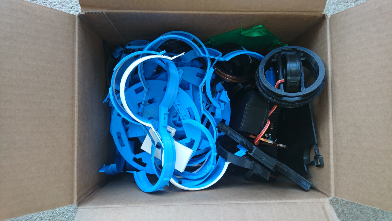
This rover, due its complexity, needed a lot of prototyping. I mean really a lot:
Prototyping

That's over 1.5kg of plastic and other bits inside...

Conclusion
Radar

This years rover ended up being quite complex. It has almost ultimate mobility with ability to rotate, go sideways and do all of it while constantly rotating. Wheels provide movement information feedback (odometers via rotary magnetic sensors) with all around distance sensors along positioning system (9 degrees of freedom sensor) provide that more informatino than we could have handled this time. PyROS got extension and now supports cluster of Rapberry Pi computers allowing them all to work together using MQTT for communications. Aside of 'important' stuff it finally gained touch screen with SciFi inspired theme GUI and audio feedback allowing playing sounds and delivering feedback in a form of a computer generated speech. And all packaged in a nice, stylistic body.

Still there's plenty to do: main motors are tiny motors used on our previous rovers which where less than 1/3 of this rover's weighs and steering motors steer wheels at the edge of usability. We didn't get to implement properly power management where whole Rover can shut down different portions of it and/or completely itself, while constantly monitoring battery voltage and current through it. Also, interior is organically grown - wire management is at prototyping stage, PCBs rudimentary. It would be really cool to try to use PCBs in wheel hubs so they have dual purpose - hold electronic components and act as wheel guards at the same time.

Software wise - it would be really nice to tighten control loops and fine tune PID algorithms. Also to provide better representation of the real world combining wheel orientation feedback along with odometer to calculate how much rover really moved and where, along with distance sensors and positioning system (gyro, accelerometer and compass). And use that data to superimpose over virtual representation of the concrete challenge. And for challenges maybe to replace some of the coded behaviours with ML and neural networks...

There are so many possibilities! So many things to improve...
YCanyons Of Mars


Canyons Of Mars

"Slow and steady wins the race" - Not sure about that, but at least we can go for finishing the race...
Following Right Wall

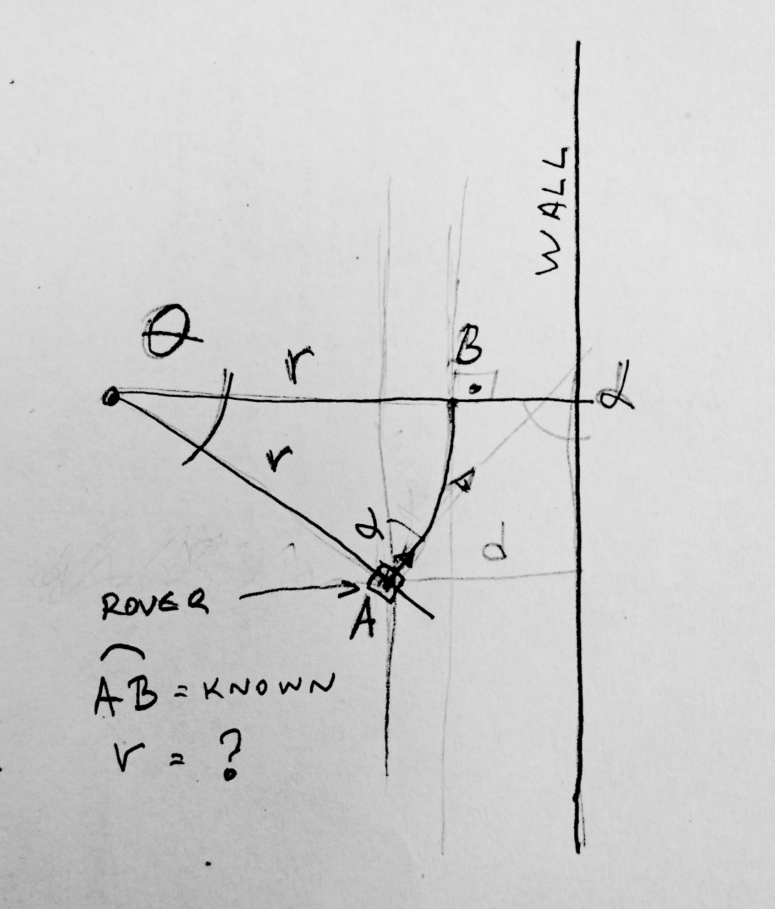
Similarly as in previous years, this brought plenty of mathematics. One was to calculate amount rover needs to steer in order to avoid the wall. Math problem is really as following:

  • if we know how much rover traverses each 'tick' (main control loop of "Canyons of Mars" is running at 10Hz),
  • if we know what is angle of rover towards the wall

we would like to calculate what is the distance of a point from rover we want it to steer around.

Oh as pictures tell thousands words:

Math Problem

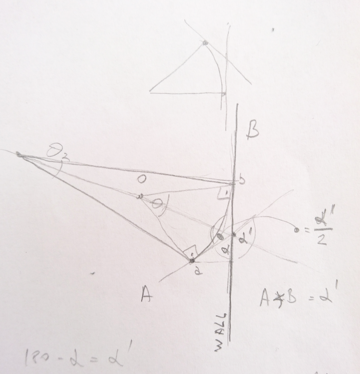
Here we know what arc size is (AB), what distance to wall is (d), angle to the wall (𝝰), we don't know what Θ is but really need to calculate r.

It was interesting seeing how our A level students tackle the problem (coming up with alternate solution and in half the time than me) and how our GCC students do the same.

Anyway - one way to solve it is given on this picture:

Math Solution

Arc length is r * Θ and using Euclidean geometry we can prove from above picture that Θ is really same as 𝝰. From there it is easy:

length of arch = r * Θ = r * 𝝰 => r = length of arc / 𝝰

And length of arch is really speed our rover is travelling.

Now by the combing distance of point we want rover to steer and angle we want rover to deflect from the wall (if it is too close or get closer if it is too far) we can get really smooth auto correction as what you can see in the video...
YPython Comprehensions


Python Comprehensions

Wev've had many posts that were mainly pictures; let's have one with some code!

Over last couple of months I've got impression that some people do not regard Python as good, modern language (well it has some of the history to make some people stop and think). As any language it has its good and bad sides along with where it can be used as a really good choice and where maybe not.

Python is quite a high level programming language which had its object orientation added relatively late and some of it reflect in somewhat clumsy syntax. But, there are some other sides of Python that put is at par with other popular languages like Java/C#, Ruby, JavaScript and such. Some of it's syntax sugar is making it even better... And that's what we'll look into here: list and dictionary comprehensions.
The problem

Our code is separated in many small processes which acquire data from sensors, inputs and such, process them and send them by MQTT messages to high level controllers that make decisions and send them to lower level controllers that know how to command wheels, and then from there to wheel controllers that steer and drive them. For simplicity originally we adopted sending messages in plain ASCII - human readable form so debug can be really easy. For instance shell command:

mosquitto_sub -v -t wheels/#

would show required positions and speeds of wheels,

mosquitto_sub -v -t move/#

would show what was required of rover to do - rotate, drive in straight line at angle or steer around some point at some distance form the rover.

Distance sensors do provide similar messages that look like this:

0:1201 45:872 90:563 135:797 180:1622 225:433 270:319 315:478

Solution

To transform it from string like that to a dictionary we can use simple code like this:

distances = {}
for entry in message.split(" "):
    split = entry.split(":")
    distances[split[0]] = split[1]

But with list comprehensions we can do better:

distances = {int(k):float(v) for k,v in [entry.split(":") for entry in message.split(" ")]}

Let's see what it really does:

message.split(" ")

is making a list of strings that are separated by given separator (an empty string here " ") and result is:

['0:1201', '45:872', '90:563', '135:797', '180:1622', '225:433', '270:319', '315:478']

Next is to take list of strings that are separated by ':' and make a list of two element lists:

[entry.split(":") for entry in message.split(" ")]

Result of it is:

[['0', '1201'], ['45', '872'], ['90', '563'], ['135', '797'], ['180', '1622'], ['225', '433'], ['270', '319'], ['315', '478']]

That's called a list comprehension. And in there we can filter elements and/or transform them on the fly. For instance, if we have a list of strings that represent numbers like this:

['1', '2', '3', '4', '5']

we can transform it to list of numbers:

[int(n) for n in ['1', '2', '3', '4', '5']]

where result is:

[1, 2, 3, 4, 5]

Also, we can transform list of numbers so we exclude all greater than 2:

[n for n in [1, 2, 3, 4, 5] if n > 2]

where result is:

[3, 4, 5]

Now back to our problem. We've produced list of lists of two elements. Now we can use those two elements and produce a dictionary using first element as key and second as value:

{int(k):float(v) for k,v in [entry.split(":") for entry in message.split(" ")]}

Also, just before using key we will transform it to int and value to float.

Result is:

{0: 1201.0, 45: 872.0, 90: 563.0, 135: 797.0, 180: 1622.0, 225: 433.0, 270: 319.0, 315: 478.0}

But we had another problem to deal with: sometimes we have data passed to us at various parts of the code as just a list without keys given - where keys are understood. For instance logging: we have record containing values that were previously logged (something like [1550348686.8102736,b'fr',b'SK',1.0,32,0.0,0.0,0.03261876106262207,0.0,0.0,0.0,0.0]) and list of fields that were used to create that record. Each field is an python class that has toString(value) and fromString(value)methods. First is to produce csv file and second to create value from csv's column.

So, to create CSV file (which we can use later on for analysing what went wrong) we would like to create a string out of record and back to create a record back of string. But our data and data definitions are in separate arrays. Ordinary solution people would normally go with (and including me before I got fascinated with comprehensions) would go something like this:

result = {}
for i in range(len(logger_def.fields)):
    result[field.fields[i].name] = field.fields[i].fromString(record[i])

But now with comprehensions we can do better. Also, in order to put two arrays together we can use method 'zip' which alternates elements from one and another array. For instance:

zip([1, 2, 3, 4], ['a', 'b', 'c', 'd'])

would give:

[(1, 'a'), (2, 'b'), (3, 'c'), (4, 'd')]

(not really - would we need to 'convert' iterator to a list with something like this

[e for e in zip([1, 2, 3, 4], ['a', 'b', 'c', 'd'])]

but final result is the same)

Now we can combine these two together:

result = {f.name: f.fromString(v) for f, v in zip(logger_def.fields, line.split(","))}

(try simple example from above:

{k: v for k, v in zip([1, 2, 3, 4], ['a', 'b', 'c', 'd'])}

)

Conclusion

Those are just one aspect of Python that make it interesting and fun to work with. There are much more to the language...

YRover's Photo Shoot


Rover's Photo Shoot

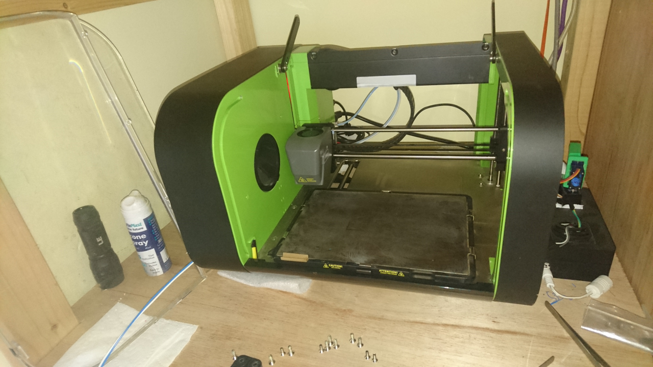
3D printing is still not as robust process as printing on paper. We tried to push creating Rover's body for the PiWars Programme but the printer just couldn't do it. Main problem was one extruder being weak (original Kickstarted extruder) and after that bowden tubes being of 'wrong' size and hang down ruining print (known problem of Robox printer) when print is tall enough.

Many hours later, printer stripped bare, 2 new set of bowden tubes created, weak extruder replaced and we are back in the game of 3D printing. Now only 3D printing - but dual material 3D printing...

3D Printing Robox3D Printing Body

3D Printed Body

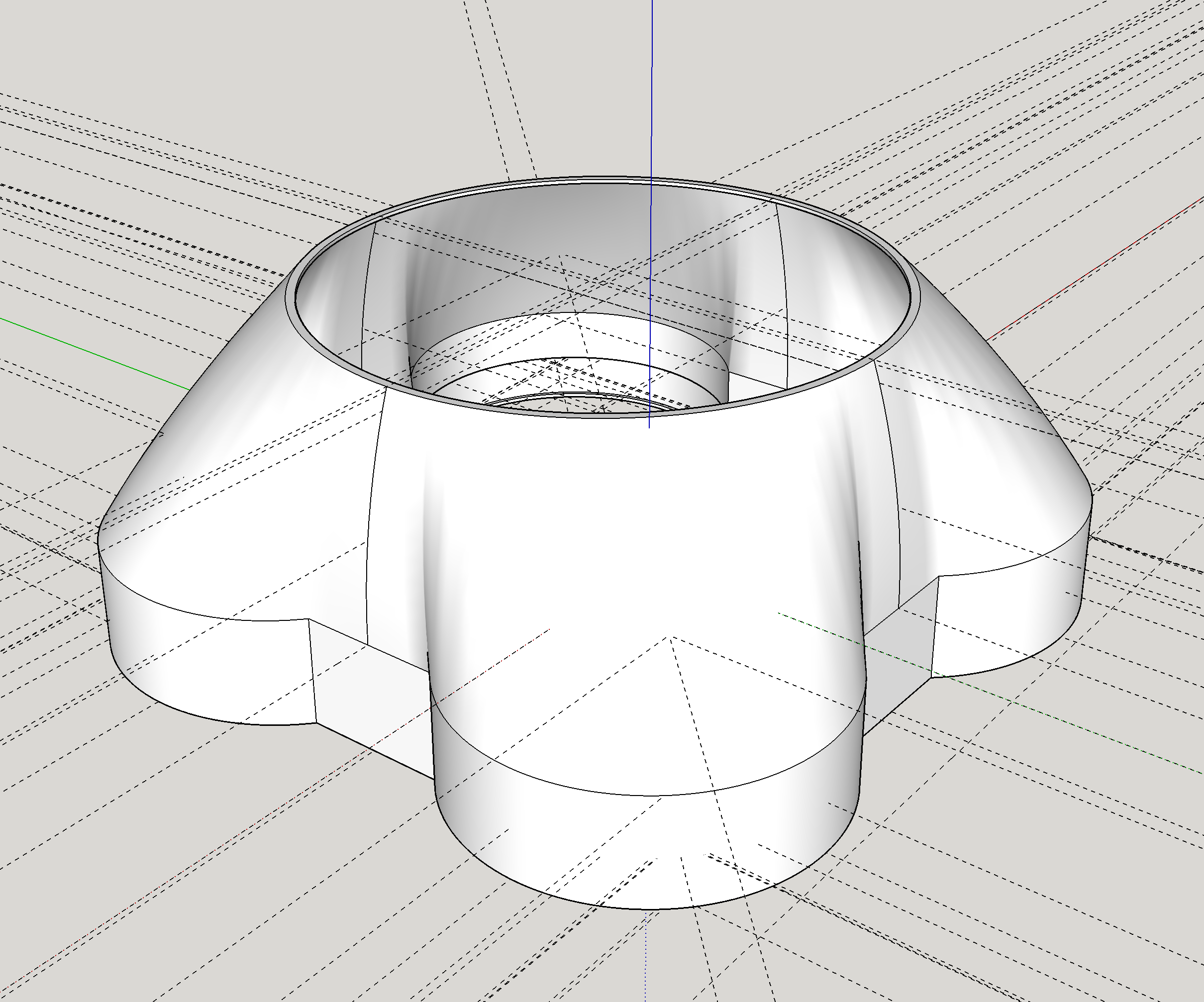
Design itself was something of a challenge. First was measuring not only the design of rover's chassis to middle tier and then to top face, but what tolerances we need to add so when all is assembled fits the reality where different half millimetre here and full millimetre there do add up.

The body is made of two sides so they can be put on the rover - clamped on it.

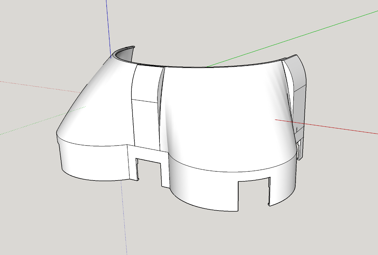
Rover's Body Design Half

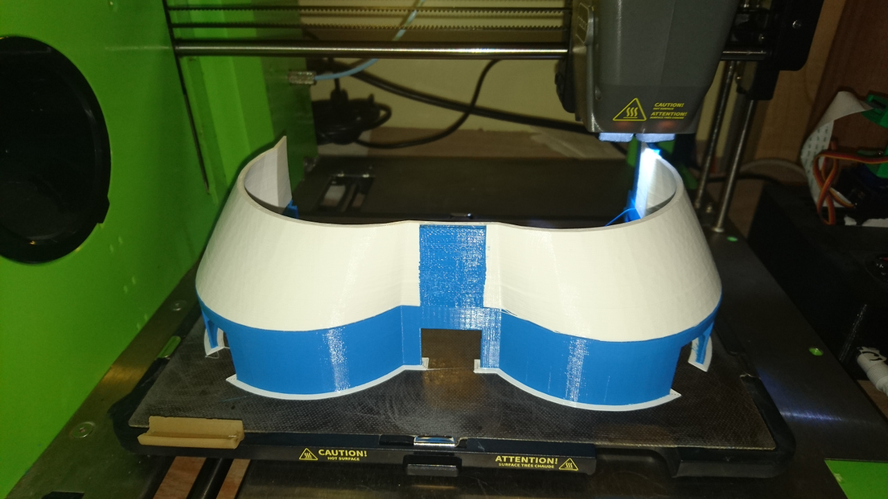
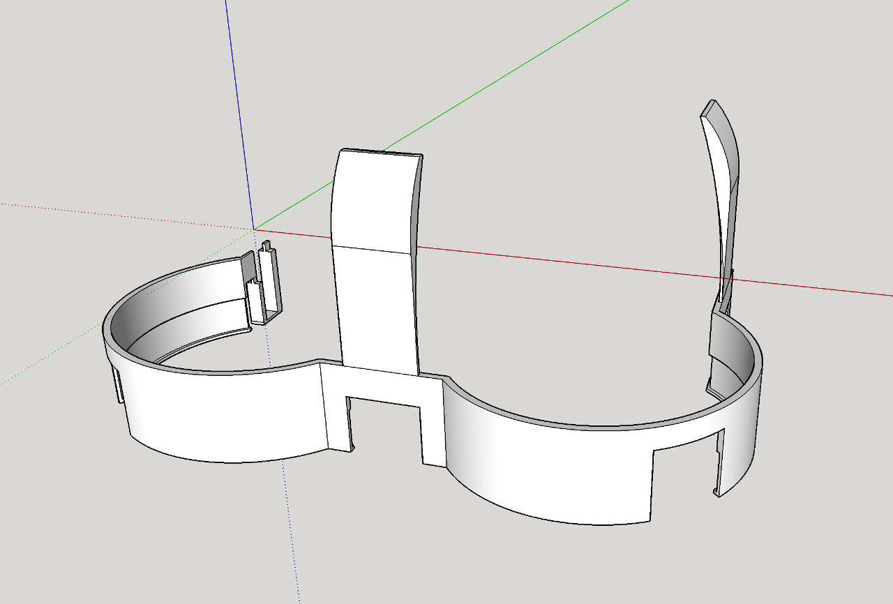
But for printing it in different colours we needed to split it to blue and white sections, so they can be exported as separate stls and then upload to printing software:

Rover's Body Design BlueRover's Body Design White

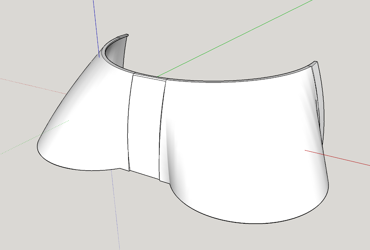
Both body halves added together look like this:

Rover's Body Design Complete

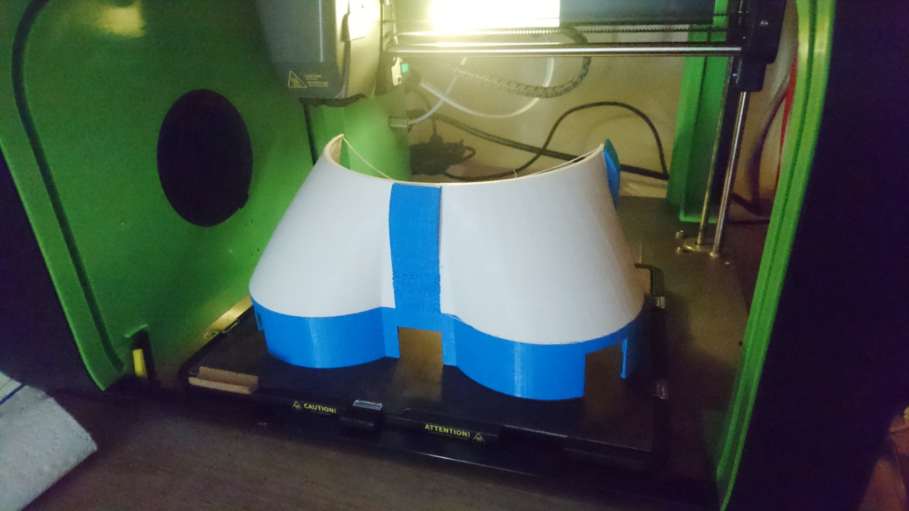
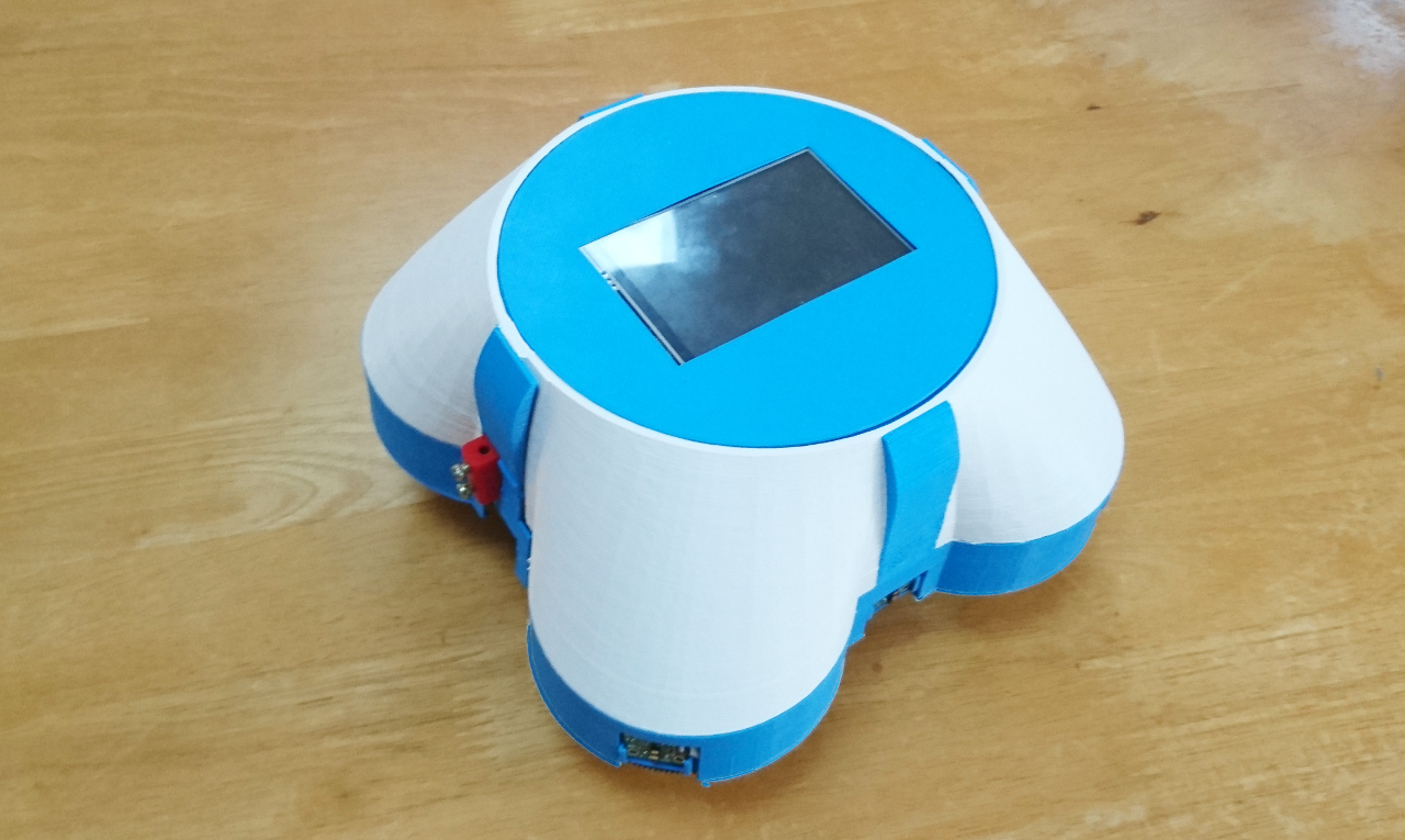
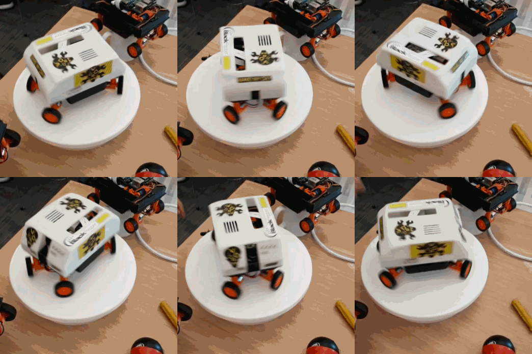
And here it is completed: Rover's Body

At least we have something to show this year in "Artistic Merit" section of scoring.

YPower Consumption And Other Woes


Power Consumption And Other Woes

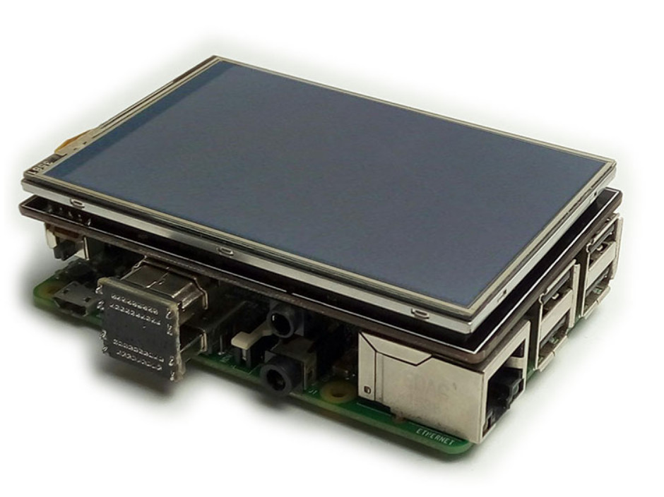
Now we have Feedback Status Screens sorted, something cropped out - pretty much immediately. Our Raspberry Pi is 3B+ model, 1.4GHz quad core ARM processor - something really fast and quick to generate heat. Since Raspberry Pi 3 we started needing heat sinks as Raspberry Pis can go really fast and generate lots of heat. Unfortunately our design isn't the best regarding heat dissipation as RPi's processor is sandwiched between RPi's PCB and the screen:

Touch Screen

When processor is taxed a lot, heat would be trapped between these two and slowly raise. With our GUI improvements not only temperature warning came up but we finally saw CPU usage - it was over 50% which translates to more than two full cores running at around 100% (or nicely spread over all cores). With such CPU usage we started hitting temperatures of CPU around 75ºC to 80ºC and at 80ºC where CPU throttling started kicking in.

High Temperature and How to Fight It

Observations provided us with the fact that the CPU doesn't really hit those temperatures immediately but over course of 5 10 to 15 minutes or more depending on ambient temperature. So, not everything was lost.

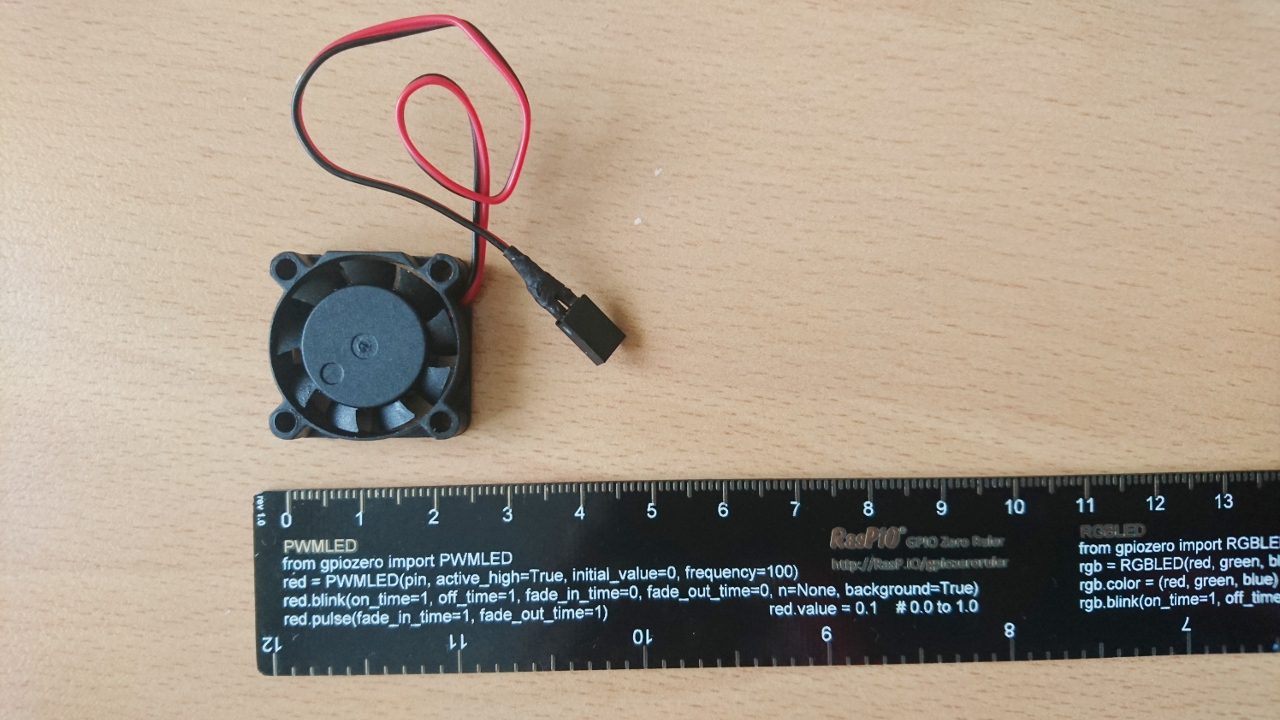
First idea was to try to add small fan which would fit in. Something like this:

Small Fan

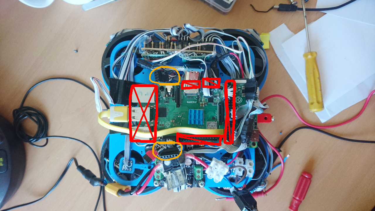
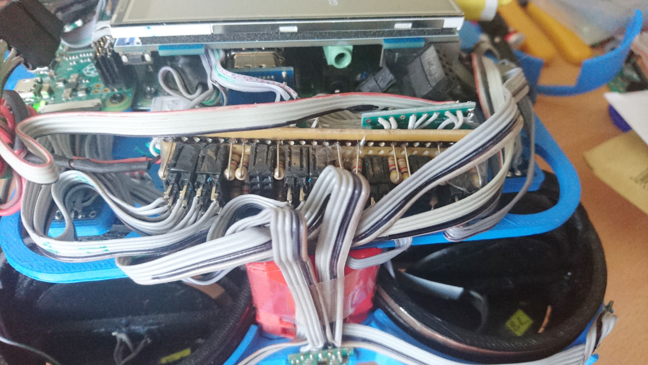
But question is - where really? Inside of the rover is quite a mess and there wasn't originally left any space for the fan, even that tiny as the one above. Here on the picture there are only two places identified: one above next to audio connector and one below: Inside Mess

But both have connectors taking places where fan would reside.

As ever - that required Plan-B: better usage of CPU. Culprit of high CPU usage was identified (position service - running data acquisition through two SPI interfaces at 230Hz+ as well as running Madgwick and Kalman filter algorithms). And that service was running all the time. So, now it got pause and resume MQTT messages. Also, all the wasteful PyROS MQTT processing(*) was toned down for services that do not need quick response like shutdown, discovery, storage, power and wifi services. They all can 'sleep' (release CPU) for longer periods of time since reacting on MQTT message on time (unlike wheels and drive service) is not critical.

Note: (*) paho-mqtt Python package that is normally used for MQTT communication has something implemented in not the best/more optimal way: it doesn't wait for socket data in a way that would release CPU, but continues to poll using CPU all the time. Even though client object's loop() method suggests some timeout and in many similar implementations around the programming languages and frameworks that means sleeping until activity - here it doesn't.

Power Sorted

With all improvements in the code we ended up with CPU usage when rover is idle at around 10% which immediately reflected on temperature - it barely went over 60-65ºC. We are expecting that position service will be needed in autonomous challenges only and for duration of the challenge - while all challenges should, really, finish without a minute in the worst case scenario.

First Breakdown

And the inevitable happened. While trying to implement following 'right wall' one of the wheels started reporting overheating protection kicking in (*). Closer inspection showed it was slower to steer than others and producing a noise that by any terms didn't sound right. It warranted nothing less but slowly taking things apart and finding out what is causing it. Worst worries were that it is one of second hand, expensive, really heavy, bearings that finally gave.

Taking the wheel apart prompted another though - designing with repairability in mind. It turns out that all the wheels are assembled from the top, then middle platform added, then many other things piled on the middle platform - so getting to the wheels requires taking top platform off (which itself is not an issue), taking many wires off (which is an issue), taking PiZero off so we can take main Raspberry Pi off just go get to screws to get the top platform off. Had those screws were on each side of main Raspberry Pi it would require no dissembling of middle platform. Then, when top platform is off - there's only power supply that needs to be disconnected (and that's only positive thing). After that, we can access wheel insides from the top... But, had we had that in mind designing the wheel hubs, main screws to take inner ports of the wheel out would have been at the bottom and one would be able to take the wheel stuff just by flipping rover up side down and taking the wheel hub apart.

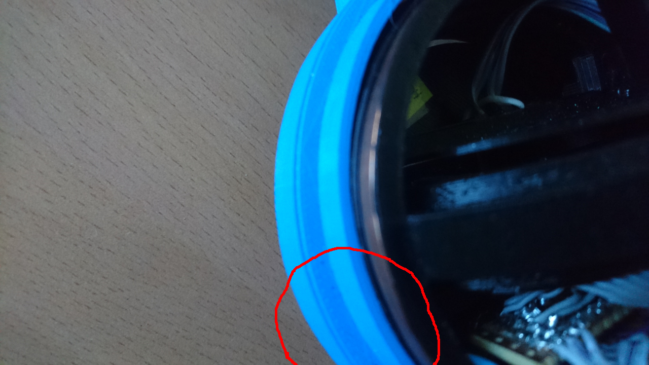
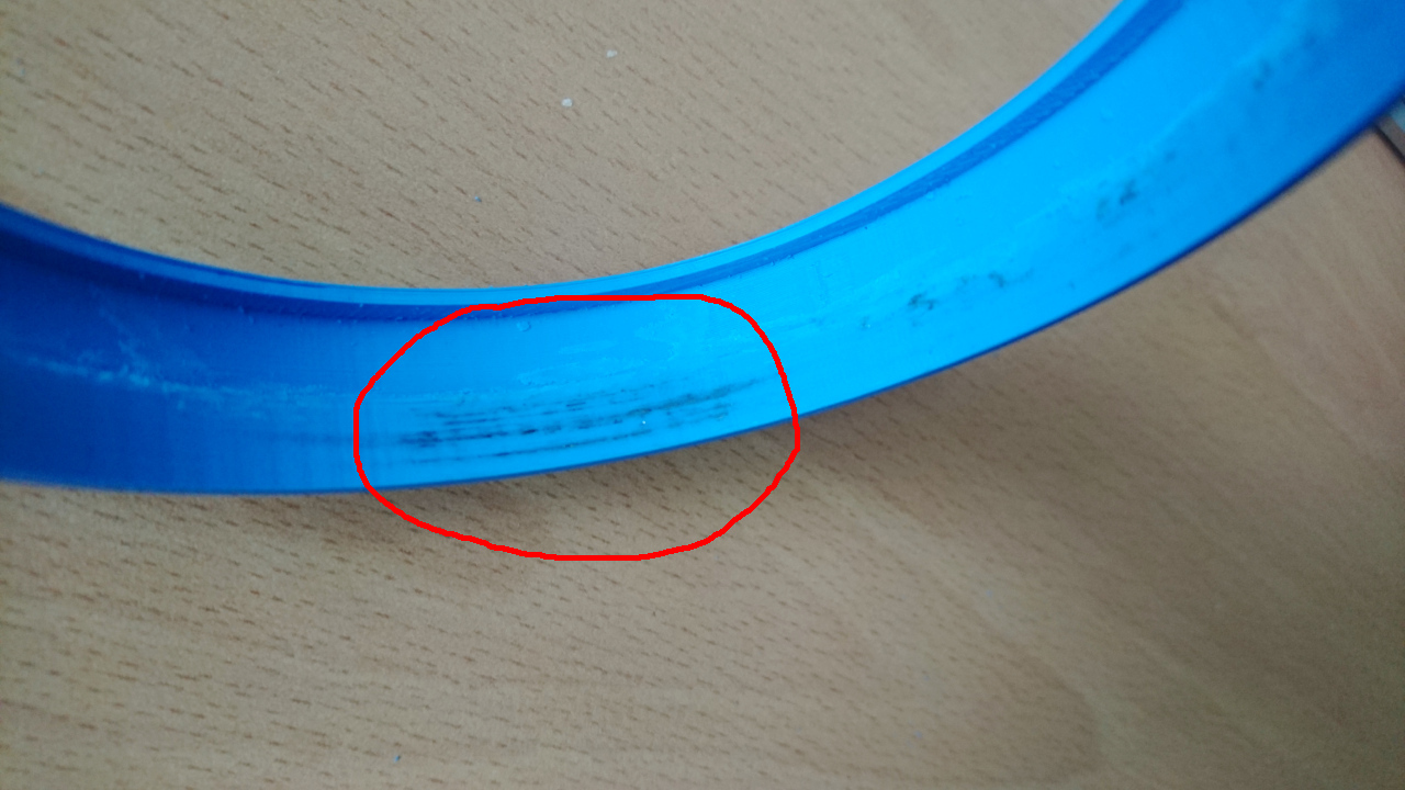
However - there was nothing wrong with the wheel hub itself. After checking how brushes push whole wheel with bearing to 'outside' it turned out that outside clamp was the one that caused all the issues - wheel hub started rubbing inside of the clamp:

ProblemInside of clamp

It turns out that original print has an error - something moved for 1mm and caused bearing to move more inside than expected and that made wheel hub to start rubbing inside of the clamp.

Outside of clamp

Odd thing is that it happened only now - after hours and hours of rover going around. Maybe it finally bumped into something which caused bearing to 'fit better' where it was supposed to be... Who knows.

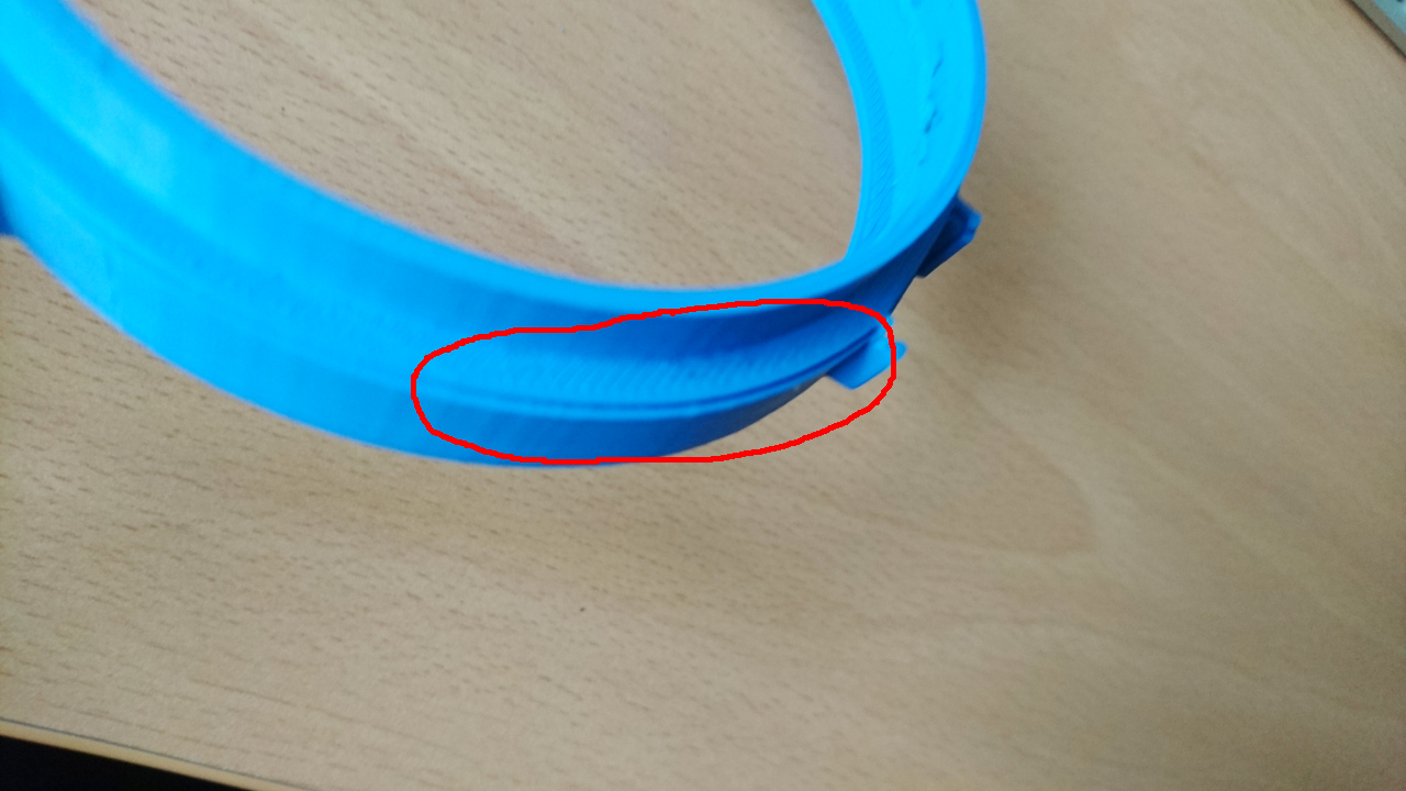
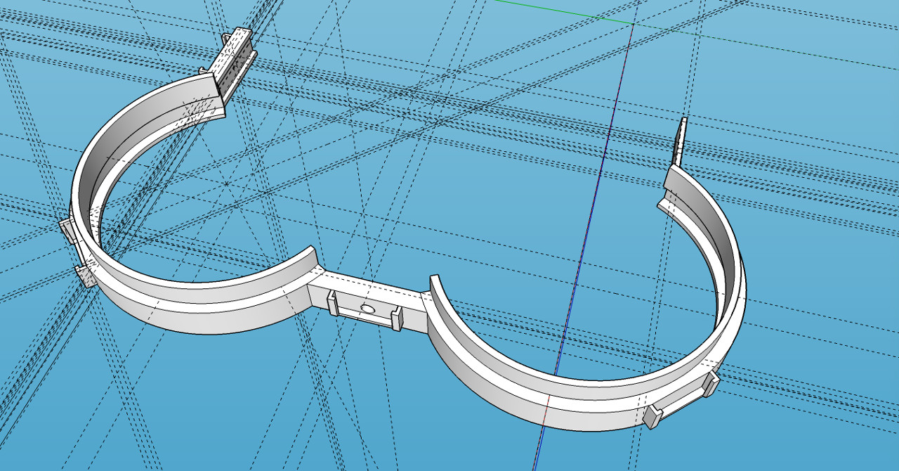
BTW this is what clamp (double one) is designed as:

Outside of clamp

Problem Sorted

Fortunately it is just a couple of hours of printing (if that much) which solved the problem. Interesting thing is that the new print has a similar error but far less announced.

YMaking Satellite Pies


Making Satellite Pies

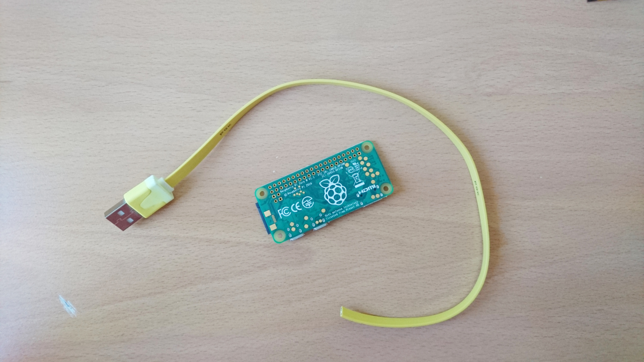
In Clustered PyROS we already mentioned second Raspberry Pi (PiZero), but didn't show how to make one. This is a quick post with picture to show how easy it is.

First we need parts:

Parts

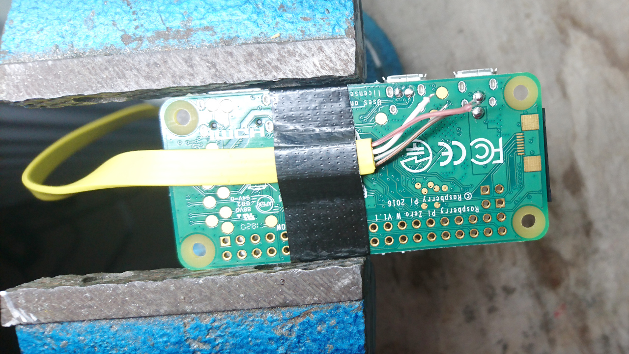
For our previous rovers we fetched 3 (or more) flat USB cables with as small micro USB side so it can nicely fit in the rover. Cutting those cables in half left us with USB A side - ideal for this purpose! Thin, flat cable works the best in this case.

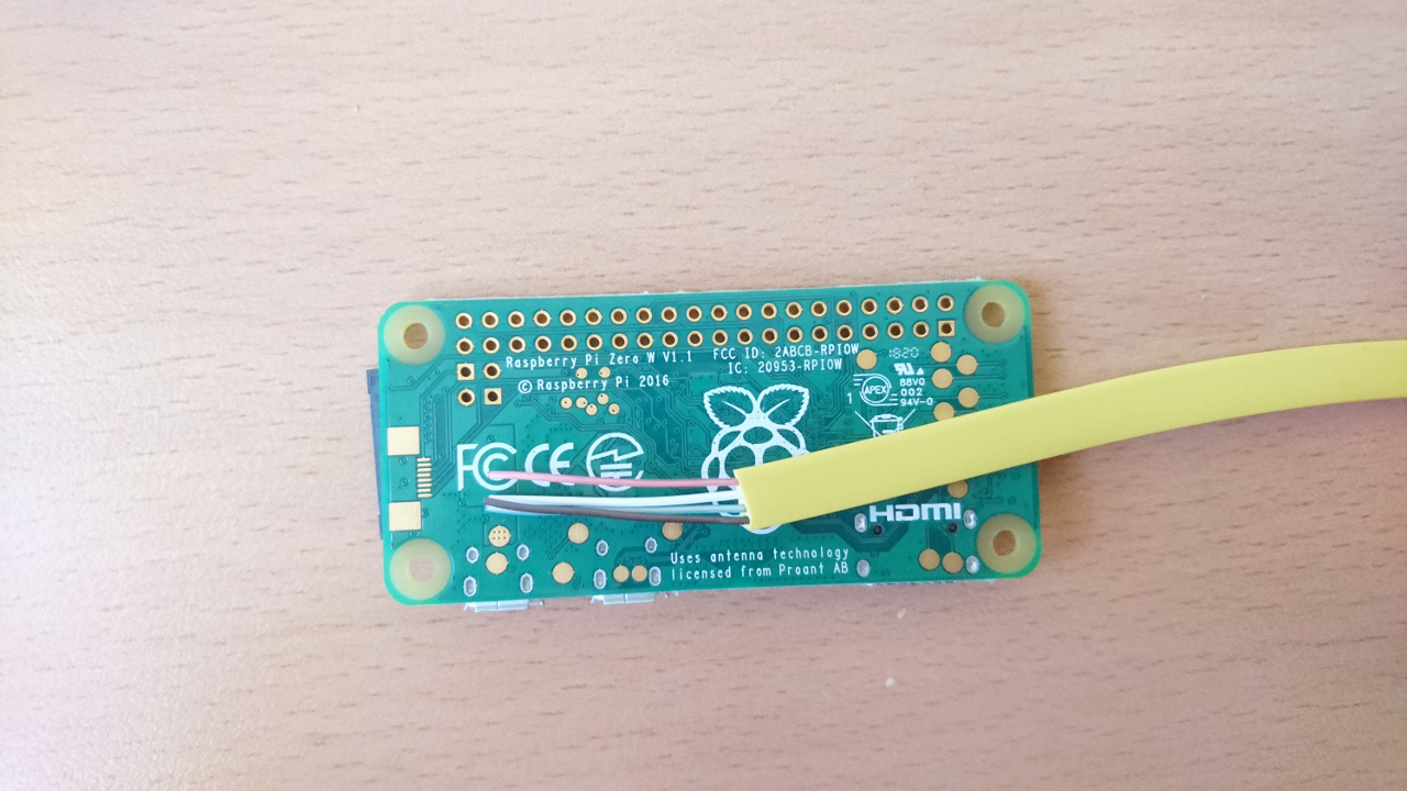
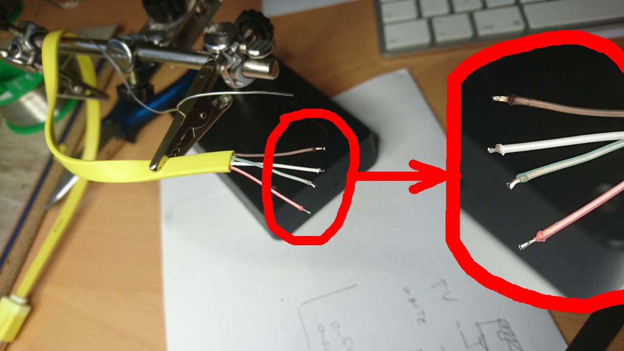
Next is to strip wires. It makes perfect sense to make them appropriate length so each wire is pretty much as long as it needed to be but not much longer.

Preparing Wires

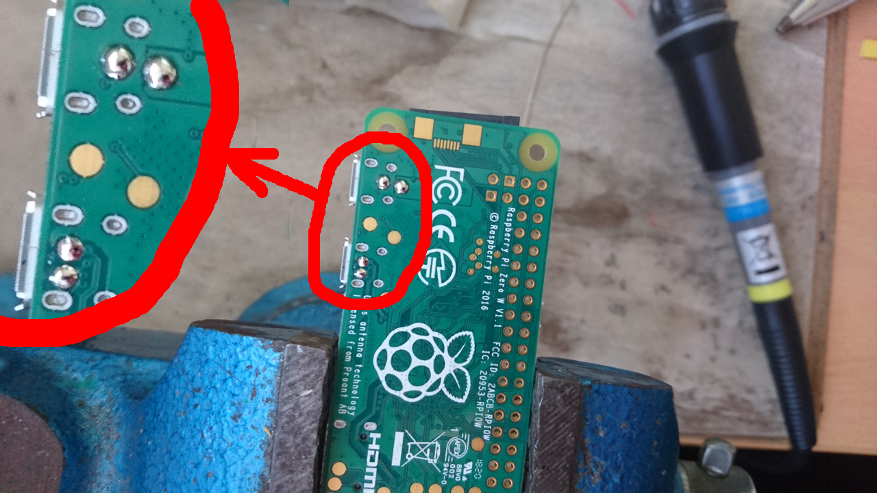
After that a small drop of tin on GND, 5+, D+ and D- pads of PiZero's.

Preparing PiZero

Same goes with ends of wires:

Preparing Wires 2

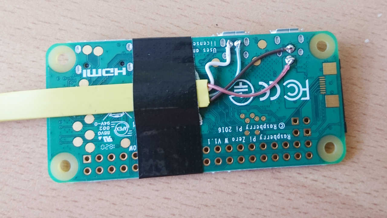
It makes sense securing USB wire before starting soldering. Piece of tape was used here:

Securing Wires

And here it is:

Securing Wires

Last thing was to secure all and maybe insulate a back of PiZero a bit:

Finished

YThis Year's Distraction - Part III - The Sound


This Year's Distraction - Part III - The Sound

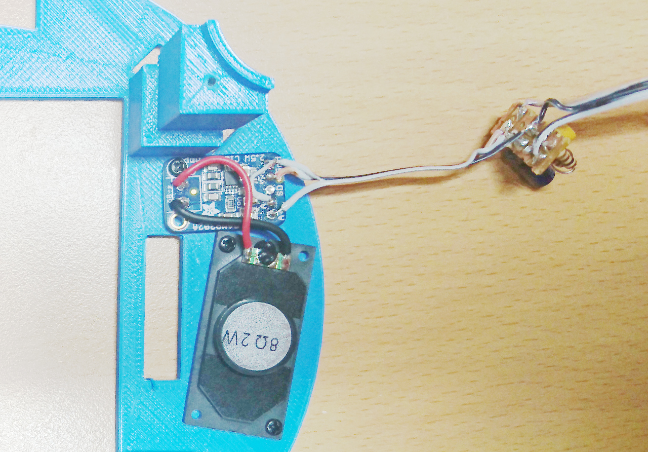
But UI itself is not enough for distraction. Rover can show nice images, we can use screen to temporarily suspend wheels operations (turning and driving), calibrate all, but... It is quite quiet stuff. What if we get tiny amplifier like this + tiny speaker that can be fitted just under the top surface of the rover? That would allow our rover having sound as well.

First is to make sure RPi is sending sound to a GPIO (there are plenty of resources on the internet explaining how to do it). Second thing is to build small filter and wire all together:

Sound System

Screen service then can gain another MQTT topic next to screen/image: screen/sound. And with following:

$ mosquitto_pub -h rover6 -t screen/sound -m alarm_system_keypad.wav

we can play arbitrary wav (or ogg - thanks to pygame).

But that's not enough. Right? If rovers are going to gain some intelligence (later, much later, I hope) then we need it to talk, too!

A quick search on the internet produced this:

http://www.festvox.org/flite/ - CMU Flite: a small, fast run time synthesis engine.

It is incredibly easy to install and use:

$ sudo apt-get install flite
$ flite "Hello!"

But original voice wasn't the best. A bit more internet searches and trying out various things produced nice, slightly disconnected - even bored, female voice called 'eey' from here: http://www.festvox.org/flite/packed/flite-2.0/voices/ (http://www.festvox.org/flite/packed/flite-2.0/voices/cmu_us_eey.flitevox)

$ flite -v -voice /home/pi/cmu_us_eey.flitevox "Shutdown initiated"

Also, to add some character and intonation to it we can use 'standard' deviation, too:

$ flite -v -voice /home/pi/cmu_us_eey.flitevox --setf duration_stretch=1.2 --setf int_f0_target_stddev=70 "Waiting for wheels to stop."

Huh. Now we have so many possibilities to give enough personality to our rover that people can get scared of it!

YThis Year's Distraction - Part II - Power


This Year's Distraction - Part II - Power

The moment we started doing some autonomous challenges code, the rover was powered by battery and problem with LiPo batteries, if someone wants to maintain their life, is that they shouldn't be over-discharged. And, since we still don't have way of checking battery's voltage, nor measuring current through it, there are couple of other ways to fudge it in the meantime: - measure time since battery was put in rover (read 'uptime' functionality of linux) - measure 'idle' current through components separately (Raspberry Pis - both RPi3B+ and PiZero and rest of the system in resting state) and then measure current when motors are driven at 100% PWM. It is easy for steering as current would be similar in case of rover going around and when on the bench, but for main wheels it is bit trickier. So we decided to 'eyeball' what it might be (somewhere between stall current and freewheeling). We do it for one wheel only...

After a session with an Ammeter, the results are like following:

Raspberry Pi 3B+ + PiZero 800mA
Raspberry Pi 3B+ only 650mA
Rest of the rover 150mA
Steering a wheel at 100% PWM 300mA
Driving a wheel at 100% PWM and some resistance 200mA

Figures are rounded up and some fudged a bit.

With those information we can re-assemble some info: we know when we drive or steer each wheel and with which PWM percentage so we can start counting (measuring time) and integrate values. It is not exact current going through the motors but much better than nothing. Results seemed to be quite positive. Here are some 'rover measured' values vs real:

rover measured (mAh) time (h) real (mAh) type of usage
1260 01:10 1100 mostly stationary
1111 00:37 780 lots of movement

Some previous measurements were in similar ranges - we always calculate more than what it really is - but relatively close to what really was taken out of the battery. So far so good.

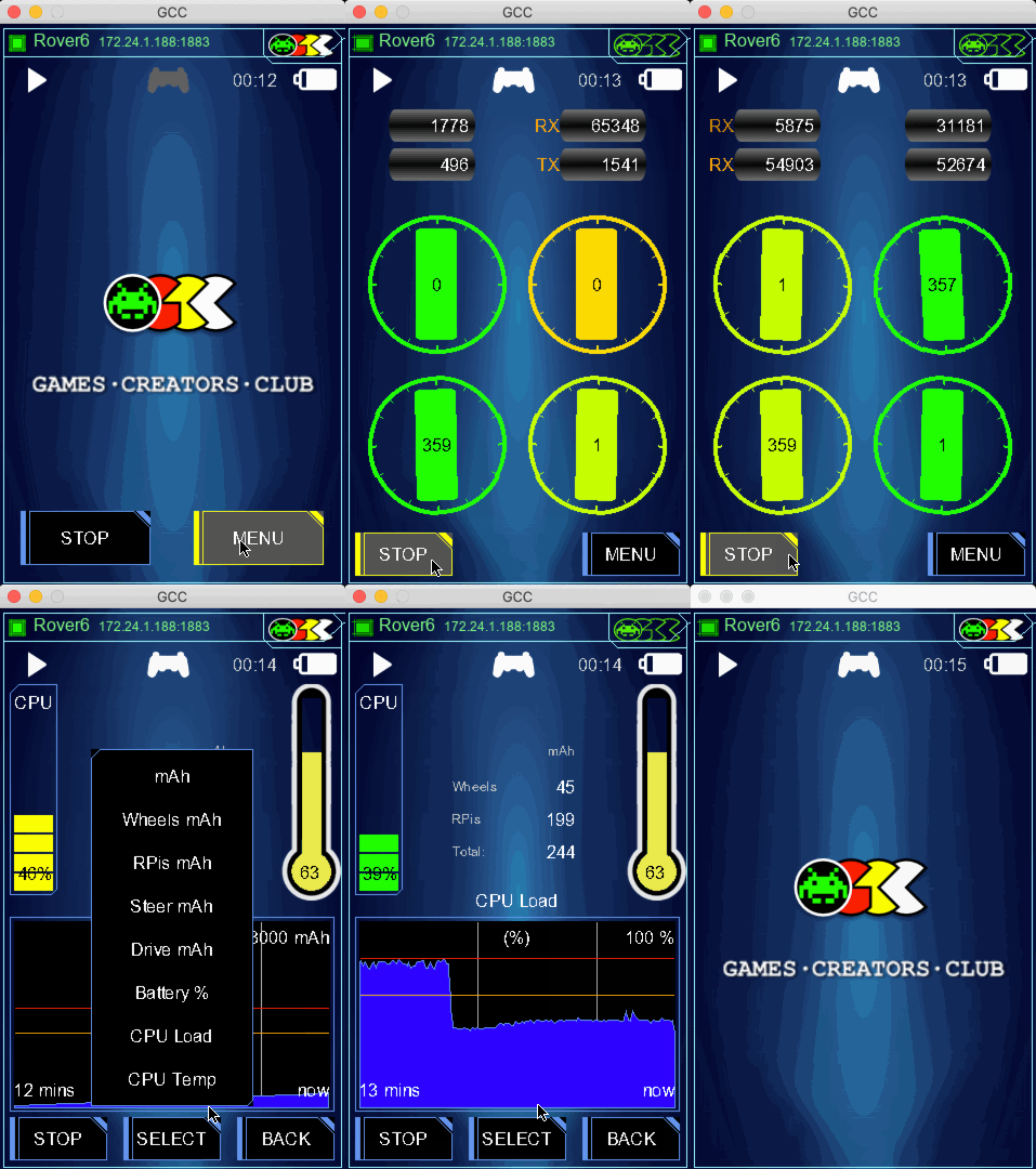
But all of it would be relatively useless if we don't have 'proper' UI to show it:

Data Collection

So we can throw in some other measurements like CPU load and temperature, too...

Client UI

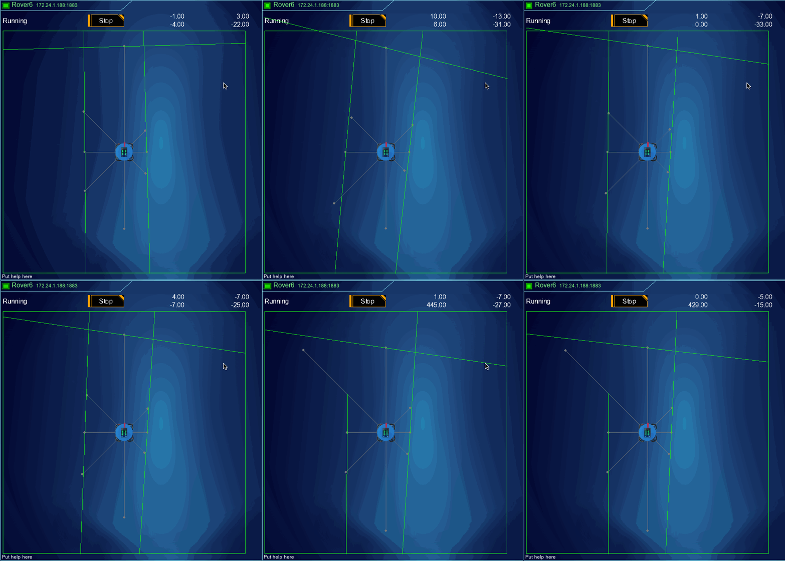
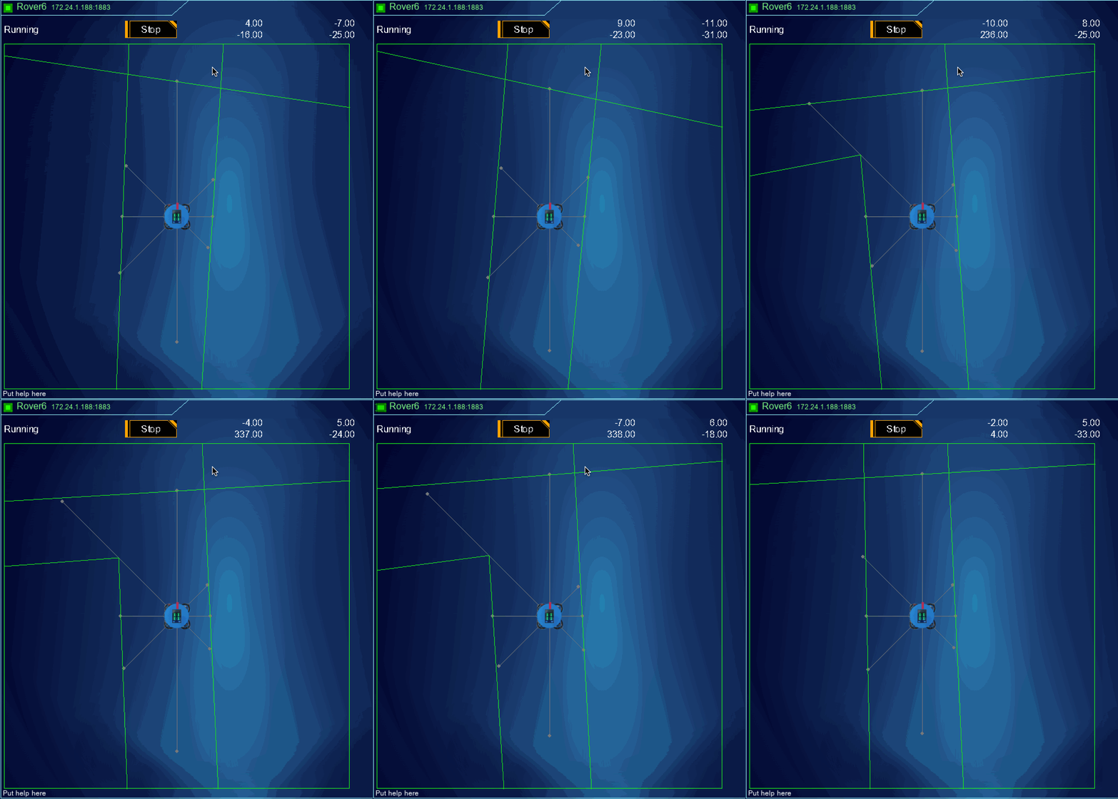
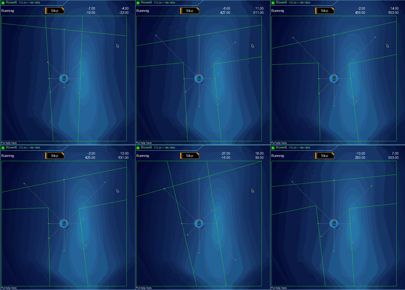
Same UI now can be applied to client apps. For instance, Canyons Of Mars client app can have feedback to what 'rover' really sees:

Maze

In this case there's a long corridor and nothing else. But, when corrner is detected (front left sensor detects point that is further left to what left wall is) then we can draw it, too:

Maze

Or if both front sensors detect points that are much further than wall lines (as seen from side plus back sensors) we can draw T junction:

Maze

In all of these examples the back wall is drawn perpendicular to the right wall. Component is just another extension of Component class with specific for this case. Also, 'connected', 'Run' and 'Stop' buttons are yet another component that encapsulates state of current agent - when it is running the component hides 'Run' button(s) (as there might be more buttons)...

YThis Year's Distraction


This Year's Distraction

As with every year there's always something that takes our attention from what needs to be done to what is really interesting doing. This year we continue with last year's theme: SciFi UI! Reason more is that this time we have 320x480 5" colour touch screen on the top of the rover. And it would be waste it not being used as intended: for shiny UI and feedback!

3.5 Touch Screen

Requirements

A touch screen on our rover is something new for us. So, what can it be used for?

  • display some status info:
    • wheel positions
    • that controller is connected
    • that rover is running or idle
    • time on battery (uptime)
    • battery status (when we finally implement reading battery voltage and possibly current)
  • display radar
  • enable calibration on the rover
  • enable setting up preferences
  • and, maybe the most important, display some funky random images during various challenges (read PiNoon for instance)

UI Library

First thing is to decide how to display it. There are a few GUI libraries for pygame for our code is all written in Python and on our Games Creators Club we use pygame for making games. But none of found libraries tick another very important box: it needs to be skinnable so we can started developing proper futuristic look and feel our rover deserves - see [last year's distraction(http://piwars.abstracthorizon.org/posts/2018/03/01/this-years-distraction/)!

Last year we did it on the client code running only, but now it needs to run on both client and rover itself...

So, since it wouldn't be proper distraction and only work on a rover itself, I decided we can make our own tiny GUI. Luckily we have a GCSE year students having Computer Science as one of the subject to help...

Structure

GUI itself is relatively easy to make something simple for start. In its the most minimal form it consists of:

  • Component
  • Collection
  • Image
  • Label
  • Button

and some code to put all together.

Component class has following methods and properties: - visible - rect - draw(surface) - redefineRect(new_rect) - mouseOver(mousePos) - mouseLeft(mousePos) - mouseDown(mousePos) - mouseUp(mousePos)

while Collection has extra property (and helper method): - components - addComponent(component)

Image is simple - it just has extra property called surface and draw methods is simple:

def draw(self, surface):
    if self.surface is not None:
        pygame.blit(self.surface, (self.rect.x, self.rect.y))

Label is extension of Image where image's surface is invalidated (set to None) and in draw method re-creating image's surface to be drawn each time in a loop. When new text is set we just need to store it (again) and invalidate image.

Button has pointer to another component (a Labal) and utilises mouse methods to check if mouse is over, down and released. When mouse is finally released it will call a on_click callback method. Also, button can have some 'decorations': - background-decoration - mouse-over-decoration

These can be set to make button's background different and to respond on mouseOver method invocations when mousePos is inside of rect of the component. Those decorations can be set by UIFactory (extensions of) and if all components are created through it, that factory can, then, decorate components (in this case buttons) accordingly. It is dead easy to create special button decorations which draw funky borders, backgrounds, etc...

Screens

So, here it is.

From this point it was easy to extend Component or Collection and add things like: - Screen - thing that can stretch over the whole screen and handle specific function, - CardCollection - a collection that will show only one of components at the time (like a tab but without a control strip of buttons)

and then specific components for the rover itself that go on different 'screens':

Main Screen

Main

Only 'Stop' and 'Menu' buttons are displayed and only for a while. They are redisplayed when there's some mouse activity.

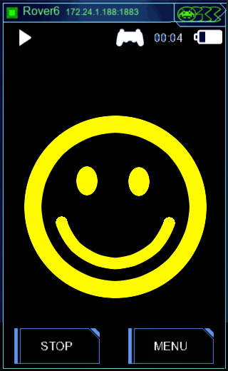
The main feature of the main screen is actually hidden from the view: ability to display any arbitrary image (uploaded with 'screen' service to the rover) when requested on MQTT topic. At the moment something like this would display smiley:

Main Smiley

$ mosquitto_pub -h rover6 -t screen/image -m smiley.png

Now our challenges can have their own background images shown...

Menu Screen

Main Menu

It displays buttons which in turn switch some other screens on

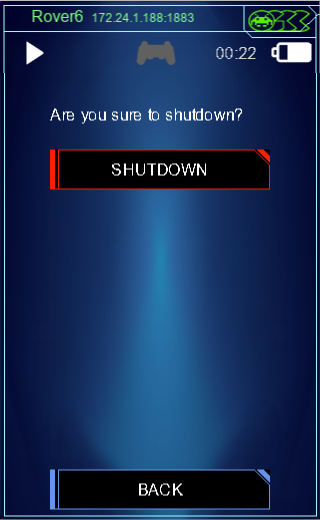
Shutdown Screen

Shutdown

It displays request for confirmation (a button) and shows label saying that shutdown is in progress.

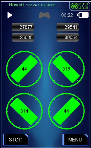
Wheel Status

Wheels Status

It shows positions of all wheels, odometer and wheel statuses (errors like transmitting or receiving errors, magnet strength or if wheel is stopped by software to avoid overheating of motor controller). We have special rover centric components for displaying wheels, odometers and such. Errors are displayed just as labels. For this function labels got colour as well, so error indicators can be displayed in various colours (orange or red) depending on how severe they are.

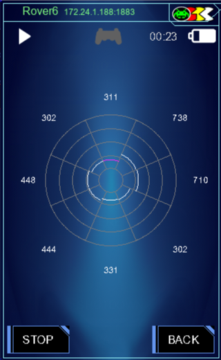
Radar

Radar

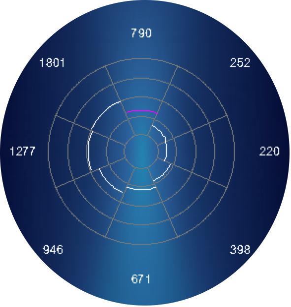
Another special component that renders the radar from 8 distance sensors.

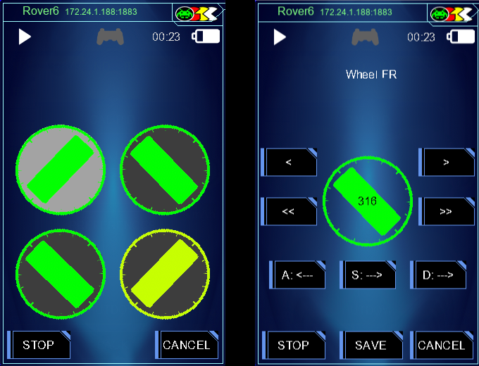
Calibrate Wheels

Calibrate Wheel

Screen that allows selection of wheel to be calibrated and then defining its orientation and position.

Calibrated PID

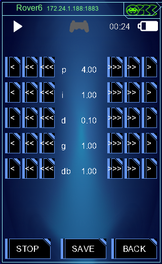
Calibrate PID

Screen that allows calibration of PID algorithm for steering wheels.

Note: (*) All pictures are screenshots of an application that runs on the client (a laptop), but exactly the same is rendered on the 320x480 screen of the rover (minus border and top bar with rover selection and GCC logo)

YAnother Setback - The Speed of i²c Bus


Another Setback - The Speed of i²c Bus

The current configuration of our buses (as explained here) assumes that one i²c on a separate PiZero is to read 4 x AS5600 magnetic sensors and 8 x VL53L1X. Reading 4 magnetic sensors worked well - sensors were read at an approximate frequency of 250 Hz. As there are four wheels (four AS5600 magnetic sensors) for each wheel it equates to controlling it 60-ish times a second.

But, as soon as we connected VL53L1X sensors frequency dropped to 10 times a second per wheel. It seems that VL53L1X is quite chatty (seen through its driver) and it swamps i²c bus for setting up ranging and reading results. Even when we wait the appropriate time and get to read after ranging is done!

Solution

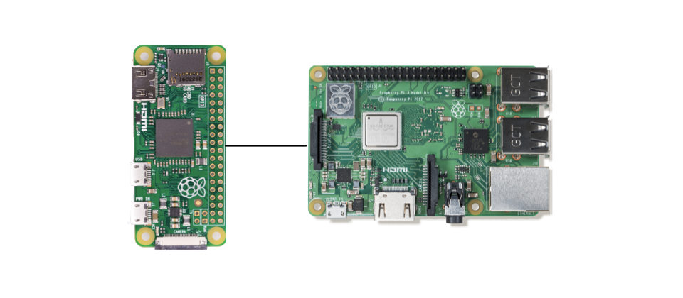
Two Raspberry Pis

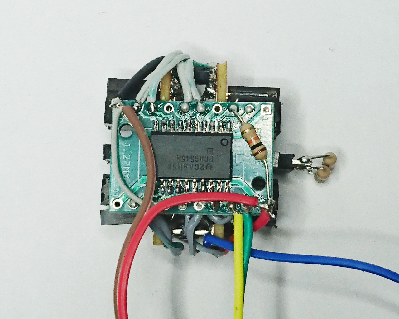
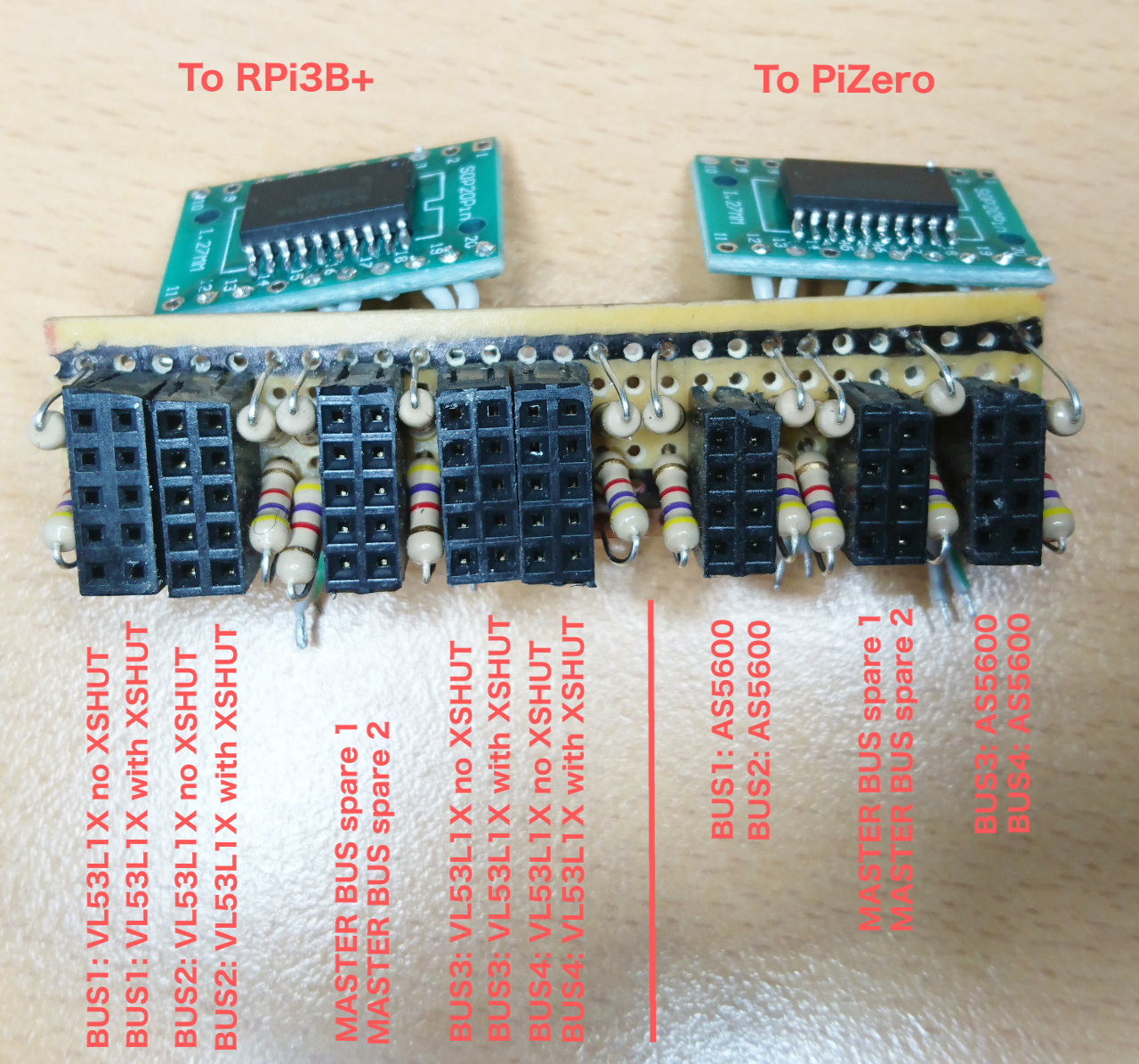
Driving wheels at 10 Hz is not really an option and we have two Raspberry Pis at our disposal: PiZero for motors and RPi3B+ for everything else. Since there's nothing else to be read from i²c on RPi3B+ we can just redesign i²c multiplexer board and introduce another i²c multiplexer for VL53L1X chips only. This way we'll use one PCA9545A for AS5600 connected to PiZero's i²c bus for As5600 magnetic sensors and one PCA9545A attached to RPi3B+'s i²c to read from VL53L1X.

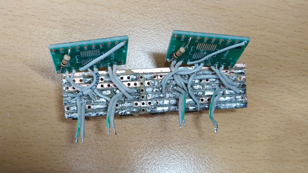
Multiplexer Wiring

This is how it was wired this time.

Multiplexer Bottom SideOld Multiplexer

The main problem this time was how to fix it back instead of the old multiplexer. It is a bit of tight squeeze there but in the end it managed to be pushed in there. Along with all the connectors. This is how it looks when mounted in the rover:

Multiplexer In Rover

PiZero now can continue controlling wheels at 60-ish Hz while distance sensors are read from RPi3B+, where, after all, they are going to be consumed by some agent. The frequency of reading VL53L1X sensors is still around 10 Hz but at least we have nice overview of what is going on all around the rover.

Radar

YVL53L1X Time of Flight Sensor


VL53L1X Time of Flight Sensor

A Low Cost Laser Range Finder

Introduction

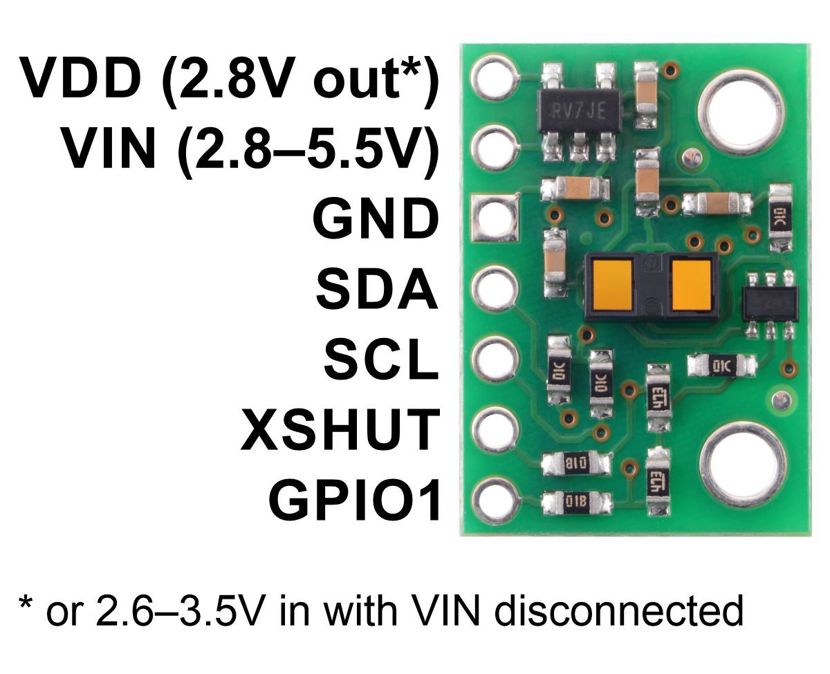
"Time of Flight" sensors are laser range finders. There are several that are available on breakout boards. We're using the VL53L1X made by ST Microelectronics for detecting walls. The breakout board we're using is provided by Pololu.

VL53L1X from Pololu

The Pololu product page provides a good overview of the sensor. It also provides links to datasheets. This blog post contains the notes I made whilst testing the sensor. I won't repeat information you can find in the datasheet.

This information is not definitive. It's just my impressions from testing a sensor for a few days.

Effective Ranges

Distance Mode Min (mm) Max (mm) Max Sunlight (mm)
Short 40 1300 200
Medium 40 2300 130
Long 250 2500 70

The minimum and maximum ranges are the points at which the sensor started reporting errors. In short and medium distance modes the sensor gives incorrect distances below 40 mm but doesn't report any errors.

"Max sunlight" gives the maximum value when the target was lit by direct sunlight through a glass window. The sensor is all but useless if the target or the sensor are in direct sunlight.

The timing budget doesn't seem to affect these distances. The material target is made of has a small effect. White surfaces can probably be detected at a longer range then dark surfaces but the effect is not very significant.

The maximum effective range falls considerably if you reduce the field of view significantly.

Ambient Light FOV Distance Mode Max (mm)
Office 16x16 Short 1300
Office 8x8 Short 1300
Office 6x6 Short 1000
Office 5x5 Short 700
Office 4x4 Short 400

Configuration

There are 3 key configuration parameters that you must set. distance mode timing budget * intermeasurement period

Distance mode determines the maximum range of the sensor. Use Short range if possible. It's faster and more accurate. Medium range is a good all rounder. Use Long range only if you have to. The data sheet says that Short is still effective in bright sunlight but my experience suggests that it isn't.

The timing budget determines how long the sensor records and analyses data. Short timing budgets underestimate the range slightly and the readings are more variable. (The standard deviation is larger.)

The intermeasurement period defines a pause between each sensor reading. Large intermeasurement periods such as 2 seconds are great if you want to save power. In our application we wanted to get readings as fast as possible. In this case there's an optimal period for each timing budget value that maximises the read rate.

Distance Mode Timing Budget (ms) Intermeasurement Period (ms) Error (%) Std Dev (mm) Freq (Hz)
Short 6.5 10 -2.5 5.3 103
Short 8.5 12 -1.3 2.6 86
Short 12.0 16 -0.8 2.2 65
Short 30.0 35 -0.3 1.2 30
Medium 7.5 11 -6.3 4.2 92
Medium 10.5 14 -3.4 3.5 74
Medium 16.5 20 -2.1 2.0 52
Medium 30.0 34 -1.1 1.4 30
Long 16.5 21 -4.7 3.9 49
Long 18.5 23 -4.7 3.9 45
Long 33.0 38 -2.3 2.0 28

Error Codes

You should reject measurements unless the measurement status code is 0 - Range Valid.

The sensor will often give reasonable looking ranges even when it's reporting errors. At other times the reported distance can be wildly erratic, swinging between min and max ranges and everything in between. As far as I can tell, the driver does a good job of telling you whether a measurement is usable. My advice is that if the driver rejects the range then you should too!

Code Description Meaning Comments
0 Range Valid Successful range All Ok
1 Sigma Fail The reading is too inaccurate to use. The driver measures the standard deviation (sigma) of the results it's getting as it builds a response. It raises this error if sigma is too high. Rare under artificial lights. Usually happens in direct sunlight.
2 Signal Fail The driver reports this if the return signal from the target is too weak to be used. Happens if the distance is too great for the chosen mode. Also common in bright sunlight. I suspect it also happens if there are too many return paths.
3 Min Range Fail ? Never seen it.
4 Phase Fail ? This usually happens when the distance a bit too far for distance mode.
5 Hardware Fail The sensor is not working. Never seen it.
7 No Update ? You'll see this if you set the timing budget too short. It also occurs occasionally in normal usage.

Calibration

All measurements were done on a single sensor using the factory calibration.

Driver

We're using the GCC-VL53L1X driver for python. This wraps the C library published by ST Microelectronics which is available from their website. The STM driver version is 2.3.1.

YClustered PyROS


Clustered PyROS

It seems that one Pi is not enough. Our rover is, now, equipped with Adafriut's 9-dof breakout board with gyroscope/accelerometer and compass modules, touch screen, 8 x VL53L1X sensors, 4 AS5600 magnetic sensors, nRF24L01 for talking to wheels and another piece of hardware that goes to SPI interface.

9-dof module can be run on i²c bus, but it might saturate it and we already have VL53L1X modules that have to be run on i²c bus. One Raspberry Pi would need to read 4 magnetic sensors to steer wheels, 8 distance sensors to determine surroundings of the rover, read compass, gyro and accelerometer to try to deduct our position (which, itself is quite CPU heavy), draw on screen and have spare CPU capacity for running PyROS and challenge code. Quite a lot and some of them (9 dof data) are time sensitive.

Here is breakdown based on which buses different devices use:

  • 9-dof can use i²c or SPI (two SPI devices - one for gyro/accelerometer and one for compass)
  • 4 x AS5600 i²c with multiplexer
  • 8 x VL53L1X i²c with multiplexer - two devices on same channel
  • nRF24L01 SPI
  • touch screen SPI
  • another device on SPI

RPi SPI

So, if we go with a 9-dof on SPI bus, then we would need 5 SPI devices attached to the same bus. Fortunately RPi allows more than default 2 devices being attached to the same bus.

Richard has cracked that as well. To have more than two devices on SPI we need device-tree-compiler:

sudo apt-get install device-tree-compiler

Next is to fetch four-chip-selects-overlay.dts file and execute

dtc -@ -I dts -O dtb -o four-chip-selects.dtbo four-chip-selects-overlay.dts
sudo cp four-chip-selects.dtbo /boot/overlays

That will add two more devices on GPIOs 7 and 8, aside of default on GPIOs 24 and 25. See the four-chip-selects-overlay.dts file.

To enable the overlay you need to edit your /boot/config.txt file to include

dtoverlay=four-chip-selects

This will assign pins GPIOs 24 and 25 to CS2 and CS3 respectively.

You can specify different pins if you want

dtoverlay=four-chip-selects,cs2_pin=24,cs3_pin=25

But, 9-dof data is sensitive and nRF24L01 is quite chatty and can jump-in in the worst possible time. So, it makes sense to offload talking to wheels to separate Raspberry Pi. If talking to wheels goes to PiZero then steering wheels can go there (4 x As5600 and 2 GPIOs per wheel - 8 in total!), too; actually motion control itself. But, since we need (can't avoid) i²c multiplexer for AS5600 sensors, then it makes sense to move VL53L1X to the same device, too.

On the main RPi we'll be left with touch screen (very low frequency, not time issues) and 3x SPI for positioning (9-dof and another device) - four it total.

PyROS

Now, since code is going to be split across two devices the question was how to mange it. On one device all is managed by PyROS:

Not Clustered PyROS

Wouldn't it be nice if the same, central control can be applied to second Raspberry Pi? Since Raspberry Pies are to be networked (look below) then there's no reason for PiZero to use Raspberry Pi 3's (B+) MQTT broker, too!

Total changes to the PyROS were minimal: each process id (name of service/program/agent) now can be prefixed with Pi we want it to go to and only PyROS main process that identifies itself with it (let's call it clusterId - or id within cluster) would react on message. Only 'global' message both react is ps command, but that's fine as result is collected from MQTT particular topic within timeout and if both respond at the same time - two messages are going to be delivered to the client and both processed and displayed. Also, if process id is not prefixed then only 'master' Raspberry Pi will react - in the same way as now.

Another simple change was to provide device identifier through exporter shell variable (CLUSTER_ID) and propagate it to all sub-processes PyROS is maintaining.

Clustered PyROS

Now, PiZero detailing with wheels is called (imaginatively, right?) 'wheels' and uploading 'wheels' service to it looks like this:

pyros rover6 upload -s -r wheels:wheels wheels_service.py

Pi Networking

As mentioned above PiZero is going to be networked with Raspberry Pi 3. The simplest way seemed to be using USB for both power and networking. Fortunately PiZeros are well know that can provide 'ethernet gadget' (or 'ethernet USB device') and that is done by adding:

dtoverlay=dwc2

to /boot/config.txt and adding

modules-load=dwc2,g_ether

after rootwait to /boot/cmdline.txt file. After attaching PiZero to Raspberry Pi 3 new network interface called usb0 appeared and automatically local-link address was assigned to both Raspberry Pi 3 and PiZero devices. But, in our case we would really like to have static IP for Raspberry Pi 3 so its MQTT broker can be easily reached. Beside that, we would really like Raspberry Pi 3 to act as gateway and NAT our access to the rest of the world. That's slightly more involved:

First we need to allow IP Forwarding by uncommenting line net.ipv4.ip_forward=1 in /etc/sysctl.conf

Next is to setup IP tables to route packets. Manually it can be done by:

sudo iptables -A FORWARD -i usb0 -o wlan0 -j ACCEPT
sudo iptables -A FORWARD -i wlan0 -o usb0 -j ACCEPT
sudo iptables -t nat -A POSTROUTING -o wlan0 -j MASQUERADE

But it is not permanent solution. The same setup can be 'dumped' to a file and that file would look like this:

# Generated by iptables-save v1.4.21 on Mon Jan 21 12:58:21 2019
*nat
:PREROUTING ACCEPT [10:739]
:INPUT ACCEPT [0:0]
:OUTPUT ACCEPT [5:572]
:POSTROUTING ACCEPT [2:344]
-A POSTROUTING -o wlan0 -j MASQUERADE
COMMIT
# Completed on Mon Jan 21 12:58:21 2019
# Generated by iptables-save v1.4.21 on Mon Jan 21 12:58:21 2019
*filter
:INPUT ACCEPT [8271:443643]
:FORWARD ACCEPT [0:0]
:OUTPUT ACCEPT [8108:437571]
-A FORWARD -i usb0 -o wlan0 -j ACCEPT
-A FORWARD -i wlan0 -o usb0 -j ACCEPT
-A FORWARD -i usb0 -o wlan0 -j ACCEPT
-A FORWARD -i wlan0 -o usb0 -j ACCEPT
COMMIT
# Completed on Mon Jan 21 12:58:21 2019

Save such file somewhere in /etc (for instance /etc/usb0_rules). Next is to ensure those rules are added at the time usb0 is attached. The New file /lib/dhcpcd/dhcpcd-hooks/80-usb0:

# usb0 up after assign ip address
if [ "$interface" = "usb0" ] && [ "$reason" = "STATIC" ]; then
        iptables-restore < /etc/iproute2/usb0_rules
fi

ensures that rules are run after usb0 interface is added. But we need to tell dhcpcd that we would like static IPs on usb0 interface. It can be done by adding following to /etc/dhcpcd.conf:

interface usb0
static ip_address=169.254.1.1/16

Now, we'll apply the same process for usb1 and usb2 and allow two more PiZero devices to be added, too. Why? Well, it is secret for now ;)

YWe Have A Movement


We Have Movement

Finally some breakthrough. The rover is now fully drivable. But that wasn't a straight forward journey. And the last let involved updating/fixing drive and wheel services.

The wheel service is responsible for steering individual wheels and driving wheels. Original code for rover M16 (with nickname 'type a' or 'type b') drove wheels using a servo signal through servoblaster daemon. This version (nicknamed 'type c') has completely different mode of delivering signals to wheels.

Steering

Each wheel is steered using H bridges to drive micro geared DC motors with feedback through AS5600 - a digital magnetic potentiometer. So, wheel service now needs to drive tiny motors to position requested (through MQTT topic 'wheels/deg' or 'wheels/all` for combined input for all wheels steering and speed details). Also, it is not just simple on/off function - motors need to be driven precisely to requested position without overshooting and one of the widespread adopted solution is PID algorithm.

Previous post (It is alive) show rover moving around, but wheel movements weren't the most optimised. If you gave command to go at bearing of 0º and then at 180º it would stop and turn wheels for 180º and drive motors forward again. Funniest thing was that it would drive motors through shortest path and some wheels would, thus, turn clock wise and some anti-clock wise. Not the most optimal solution. Correct thing turns to be checking if required change in wheel's orientation is less or more than 90º. If less than 90º then wheels should move to that new bearing. If over 90º then smaller angle would be (180º - required angle) shorter path but wheels should start spinning in opposite way. So, for state of wheels we now have:

(ϴ, direction)

and our operation to move it to next bearing can be defined like this:

                          if |ϴ - ϴ'| ≼ 90º then (ϴ', direction) 
(ϴ, direction) ⨂ ϴ' ⟾ {
                          if |ϴ - ϴ'| > 90º then (180º - ϴ', -direction)

(where ϴ is existing angle, ϴ' new angle and ⨂ means "drive to new bearing of ϴ'")

With that knowledge it was easy to fix the wheel steering movements.

Driving Wheels

Second responsibility of wheels service is to drive main motors to move wheels themselves. Unlike simple setting up servo signal for brushed ESCs to drive main motors, now we have two more hops to go over: wheels service needs to 'command' each wheel using nRF24L01 to send request to each wheel with required speed and collect response which will let us know current position and status of each wheel. See our previous post for Hub Controller

BTW current implementation is somehow rudimentary - we are just sending PWM value - following implementations should implement PID algorithm for maintaining required speed adjusting PWM on the wheels themselves.

Top Platform

Since this post has no pictures so far, let's share some of a "Top Platform" and wiring:

Wiring Top 1Wiring Top 2

. . .

Wiring Inside 1Wiring Inside 2

. . .

Wiring

Fuse

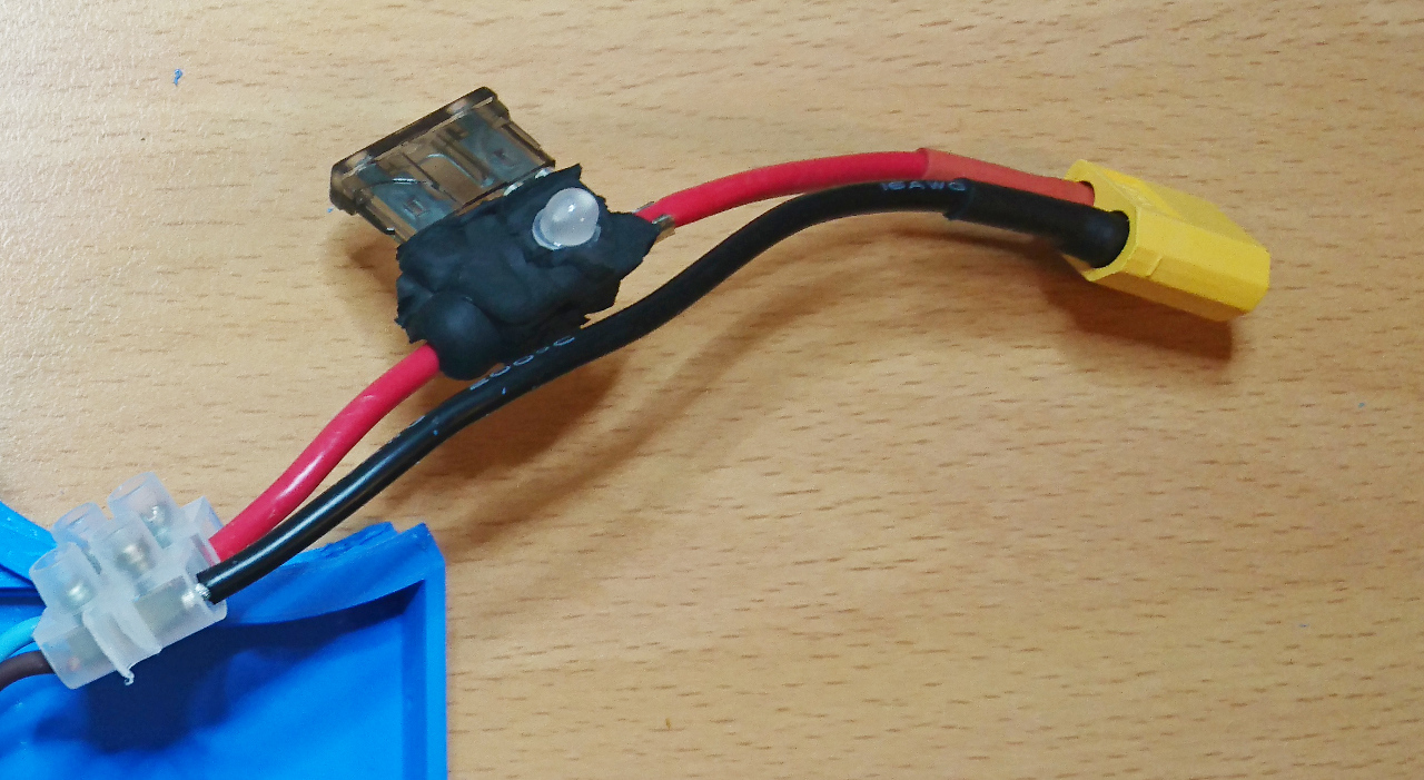
And one more thing - it is never too much when you are cautious with LiPo batteries. That's the reason all our rovers have a fuse installed:

Wiring

The main reason for it is custom wiring. In case there is a short of any kind, and power source for RPi is connected to battery directly, along with distribution wires for H bridges that steer wheels and last but not least slip rings and brushes that transfer power to wheel hubs. Any of those along with connections can potentially cause a short. And LiPo batteries can deliver quite a high current burning wires, but what's even worse - internally as well making them hot to the point they can explode. So, as it is "better safe than sorry" our rovers are protected with car fuses. Now, it is on us to measure total current rover normally pulls and provide appropriate fuse size. Currently we only have 5A...

YTelemetry


Telemetry

There are a few ways of developing your code on Raspberry Pis for PiWars: - write your code on Raspberry Pi using monitor and keyboard attached to the RPi - write your code on Raspberry Pi using ssh - write your code on Raspberry Pi using X11 tunnelled back to your computer/laptop's X11 Terminal (client program) - write Python on your laptop/computer, copy it to Raspberry Pi (scp/samba/...), ssh back to RPi to run it - use sophisticated IDEs like Pro version of PyCharm that know how to execute Python code remotely piping shell output back to IDE's console - use PyROS

I've enumerated options from simplest to most complex and from least convenient (it is quite hard chasing your rover with monitor and keyboard in your hands while attached to it) to most convenient. Having IDE doing heavy lifting for you (Pro version of PyCharm) is very useful but it costs money (£70 a year for individuals). Using PyROS is almost as easy as IDE - at least can be made easy.

$ pyros myrover upload -s -r -f wheels wheels-controller.py

This would be an example how to upload new version of 'service' wheels (python file wheels-controller.py) and keep the 'connection' on (-f option) - pumping 'logs' (stdout) back. If at any point you stop it you can continue monitoring stdout from a service by:

$ pyros myrover log wheels

But, all those predicate you use print statements in Python to log what is going on with you code. In case (as it is ours) we have a few loops running at significant speeds (over 200Hz) gathering data (from AS5600 for wheel orientation, accelerometer, gyroscope and compass from IMU and such). Just imagine the amount of text printed out all the time to stdout. Also, as PyROS utilises MQTT for communication between processes (and shell commands as above) it would make output really big and 'clog' network throughput. Additional problem is that not all output is coming from the same PyROS 'service' (an unix process maintained by PyROS) - so you would need to simultaneously monitor several process logs.

Requirements

One option would be to write to log files. But, then, how far you can go with writing to SD card? It has limited throughput as well. Then you would create several files, which would need to be downloaded after the run and analysed in parallel. Not an easy job. All of this lead us to decide to create simple data gathering system - a simple telemetry library!

Ideas were like following: - ability to define the structure of data - ability to 'pump' larger amounts of structured data to the logging system - ability to fetch data on demand from client/analysing software - nice to have: ability to produce aggregate of gathered data for real time telemetry

So, here it is - small side project of Games Creators Club: GCC-Telemetry

Design

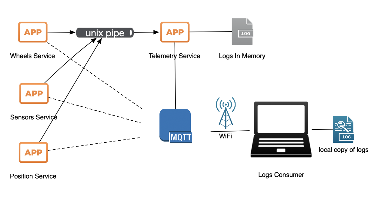
Telemetry Diagram

This is high level overview how GCC-Telemetry works: each process has two 'channels' of communication to central 'telemetry' service. One is 'general', low bandwidth used for setting up a 'stream' of data (stream of records of same type) and one is as fast as we can devise - an unix pipe to log data. Second channel is supposed to be as quick and unobtrusive to the system as possible. It would be unfair for rest of the system to suffer from a few services dumping larger amounts of data to the centra place (telemetry service). Unix pipes seem to be one of the fastest means of interprocess communication - especially if shared memory is not easy option due to several processes needed same service. Local sockets seem to be ever so slightly slower and still are kept as a 'Plan-B', a fallback solution in case it is needed. Also, sockets would work across more Raspberry Pis, too.

The telemetry service, then collects all the log records thrown at it and stores them in the memory. Since most of the PiWars challenges last around 10min max (600 seconds) and if we extrapolate amount of data to example of 200Hz feed or 20-ish float point numbers (double precision - 8 bytes long) each record would be 160bytes x 200 times a second x 600 seconds ~= 18MB - amount of memory we can sacrifice for logging. PiZero is quite tight with memory but 50-100MB (in the worst possible case) is something that can be put aside for logging if really needed. The downside of keeping it all in memory is losing data in case of a process dying or PiZero browns out before data is extracted. There's still option of storing that data slowly (for example at half the SD I/O throughput) to SD card, but it is not implemented. Yet.

The last piece of the puzzle is a client that can request data when convenient (and won't affect finely tuned software and sensor processing) - at the end of the run or trickling data through the run. Client would use MQTT (as rest of the PyROS architecture) and fetch each stream of data to local memory and do something with it.

Stream

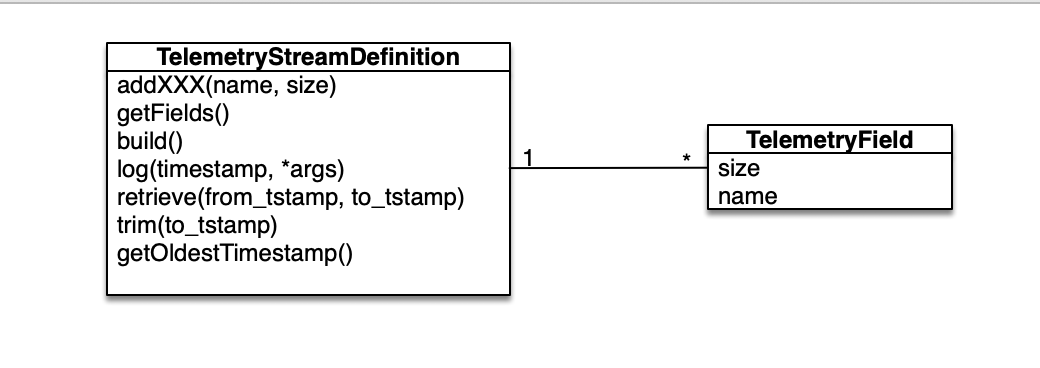
Telemetry Stream Class Diagram

Stream is defining something like fixed size record of byte fields. Using TelemetryStreamDefinition class you can define your stream by giving it a name in constructor and then define fields by calling addXXX methods (addByte, addDouble, ...). Available types (and methods) are:

  • addByte(self, name, signed=False)
  • addWord(self, name, signed=False)
  • addInt(self, name, signed=True)
  • addLong(self, name, signed=True)
  • addFloat(self, name)
  • addDouble(self, name)
  • addTimestamp(self, name)
  • addFixedString(self, name, size)
  • addFixedBytes(self, name, size)
  • addVarLenString(self, name, size)
  • addVarLenBytes(self, name, size)

Unfortunately variable length strings and variable byte arrays are not yet implemented.

Logger

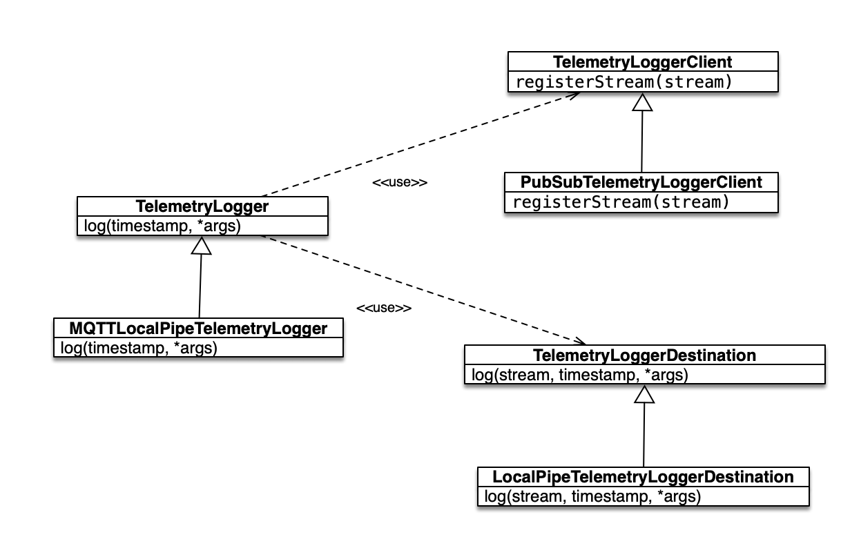
Telemetry Logger Class Diagram

Stream on its own is just an definition. In order for that definition to be put in use we've extended the class to get StreamLogger. Stream logger is main entry point for processes that need to store telemetry data to the system. Also, we can use logger to define stream. For instance:

For example:

        steer_logger = telemetry.MQTTLocalPipeTelemetryLogger('wheel-steer')
        steer_logger.addFixedString('wheel', 2)
        steer_logger.addFixedString('action', 2)
        steer_logger.addDouble('current')
        steer_logger.addByte('status')
        steer_logger.addDouble('speed')
        steer_logger.addDouble('pid_last_output')
        steer_logger.addDouble('pid_last_delta')
        steer_logger.addDouble('pid_set_point')
        steer_logger.addDouble('pid_i')
        steer_logger.addDouble('pid_d')
        steer_logger.addDouble('pid_last_error')
        steer_logger.init()

Telemetry server is going to reject new stream created with different definition for exactly the same stream name. You can defined exactly the same stream on two different places and send interleaving logs in.

When stream was successfully created we can then use it to log our data in through log method. For instance:

steer_logger.log(time.time(), bytes(wheelName, 'ascii'), STOP_OVERHEAT, curDeg, status | STATUS_ERROR_MOTOR_OVERHEAT, speed, pid.last_output, pid.last_delta, pid.set_point, pid.i, pid.d, pid.last_error)

Server and Storage

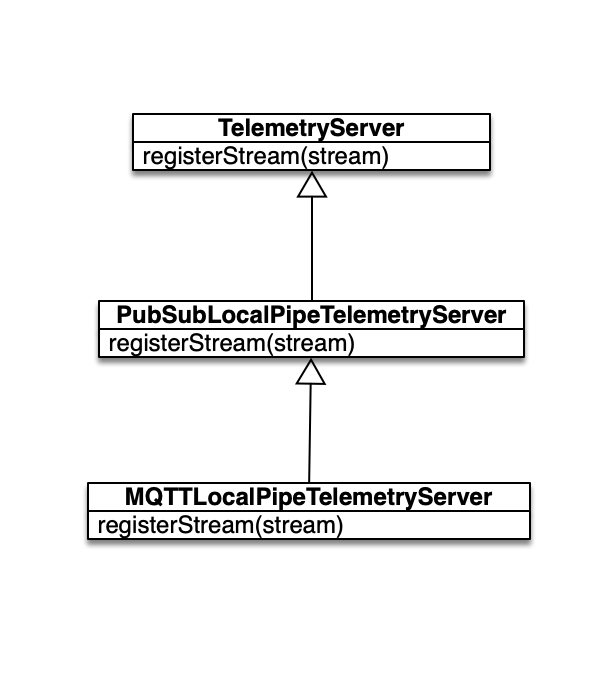
Telemetry Server Class Diagram

Telemetry server needs to be started as an service (a process for instance or a separate thread) to collect and keep data.

        server = MQTTLocalPipeTelemetryServer()

That will subscribe to appropriate MQTT topics (you can change prefix but default is 'telemetry/') and start listening to requests. Also, server needs two more details: where data is stored (TelemetryStorage) and how data is collected. For instance PubSubLocalPipeTelemetryServer constructor has following defaults:

    def __init__(self, topic='telemetry', pub_method=None, sub_method=None, telemetry_fifo="~/telemetry-fifo", stream_storage=MemoryTelemetryStorage()):

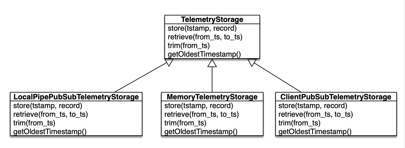
There are three kinds of extensions for storage: - MemoryTelemetryStorage - it stores all data to local array (you can limit number of records, by default it is limited to 100000) - LocalPipePubSubTelemetryStorage - was to be used with TelemetryLogger but it was implemented in a simpler way - ClientPubSubTelemetryStorage - clients that want to add to log storage remotely (not used)

Telemetry Storage Class Diagram

Client

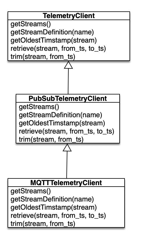
Last component is client TelemetryClient class which is to be used on laptop/computer to retrieve logs.

Telemetry Client Class Diagram

Methods are:

  • getStreams(callback) - retrieving all defined streams
  • getStreamDefinition(stream_name, callback) - getting stream definition
  • getOldestTimestamp(stream, callback) - finding out what the oldest timestamp in the set of logs
  • trim(stream, to_timestamp) - removing all logs older than given timestamp
  • retrieve(stream, from_timestamp, to_timestmap, callback) - retrieving all records from given timestamp older than to_timestamp

As you can see all methods have a callback method that is going to be invoked when data from the server are ready. An example is in download-stream - a utility that downloads particular stream from the server into a file. You can choose byte representation or CSV (human readable) representation.

Conclusion

Python is OO programming language (Object Oriented) it was quite easy to make a simple logging system. Also, `struct' built package allowed bandwidth reduction of logged data (in comparison to ASCII representation) as all numbers can be packed as bytes, words, integers, longs, floats and doubles (as unsigned as well) allowing a smaller memory footprint. After all - it was quite a fun playing with code for this small library.

Currently the main implementation is over MQTT (which PyROS heavily relies on) and UNIX Pipes. It is now quite easy to extend it for logging to happen over IP sockets (for logging over different machines); replacing MQTT with some custom implementation that can go over same sockets; add REST implementation for low bandwidth communication and such...

YMaking Brushes


Making Brushes

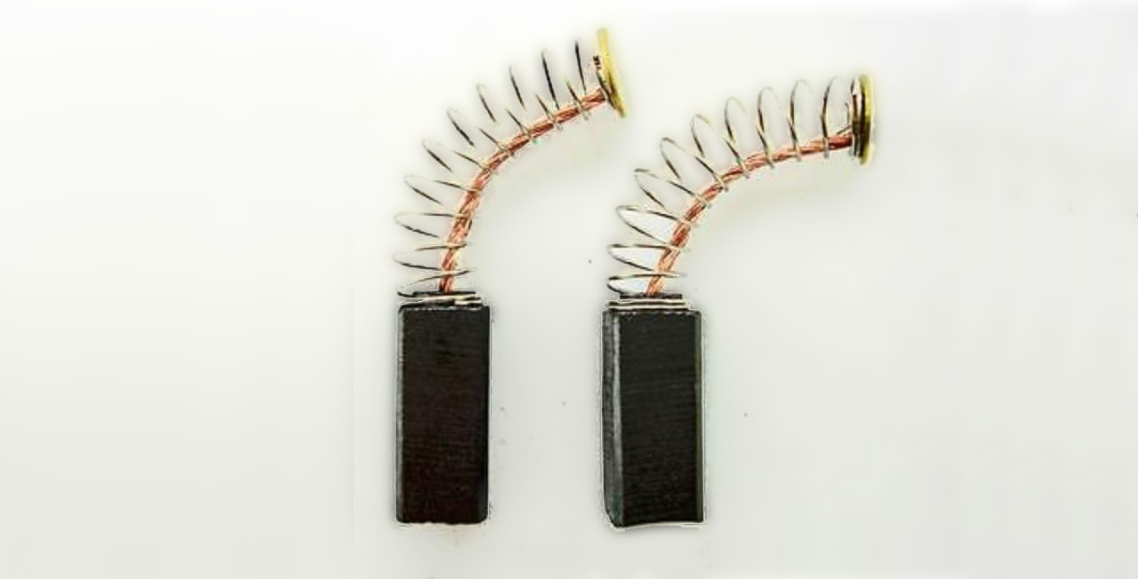
The last bit that remains for ensuring constant delivery of power to the wheels are brushes. A friend of GCC, practically a team member Saša (he provided us with 3 way sonic control breakout board we, end the end, didn't get chance to use as such - but as breakout board for driving servos for the nerf gun) suggested that brushes should follow what we normally see in mechanical relays and real motor brushes: instead of insisting on contact of a flat plate we should provide more of a spherical shape of the brush. That would allow it to overcome tolerance issues we have with 4mm slip ring, 3D printing and such and provide nice contact.

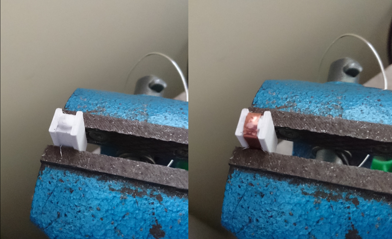
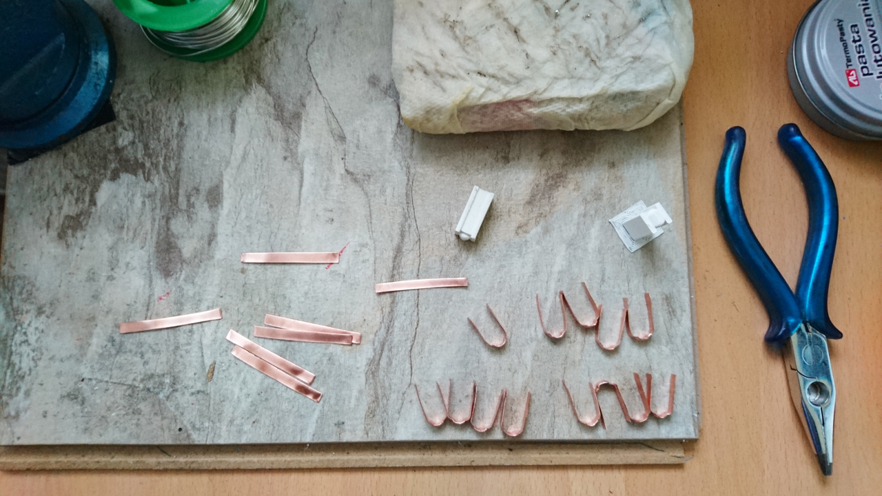
So geared with that idea we came with a solution: a tool that can help us shape 0.3mm x 4mm copper strip to appropriate shape needed - needed not only for spherical 'bump' but rest of it to fit nicely into our 'spring and brush' holders. here's a 'Brush Tool':

Making a Brush

There are 4 inner brushes and 4 outer brushes. Each wheel has two brushes - in case one at one portion of copper ring doesn't have appropriate connection other would 'take over':

Making Brushes

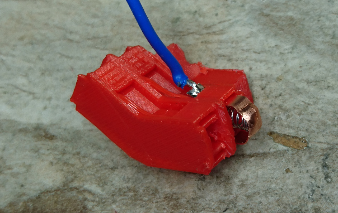
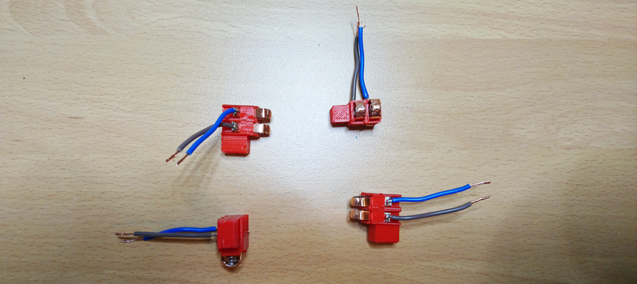
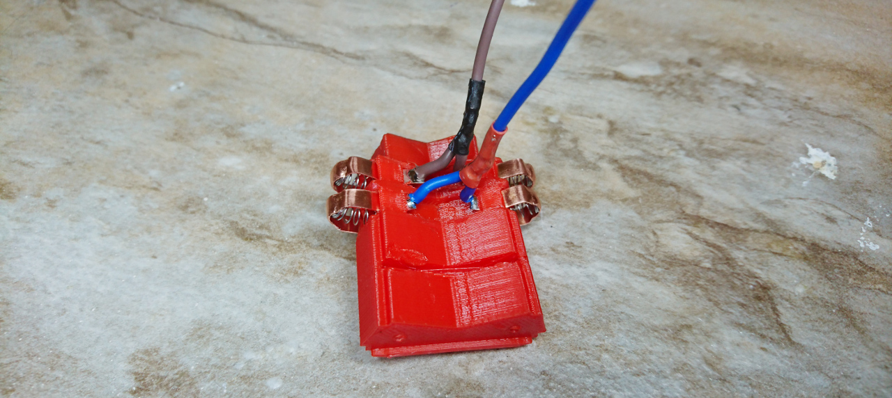
When the brushes were done, there was another question to answer - a test to be done to ensure we don't need a "Plan B" there as well: is it possible soldering a wire to a brush that is already in place - in a brush holder? Quick test and here it is:

Brush Example

Plan B might have been dunking all in a cold water leaving only small amount of copper strip out hoping that water would dissipate heat before it starts the melting plastic it is touching. Fortunately, with enough flux, it was relatively easy to solder it. Also, we would first put a solder to the end of the brush, sand it down back to almost copper, slid it through and re-solder wire. Since there was already some tin on it was much faster to solder wire and not overheat copper strip.

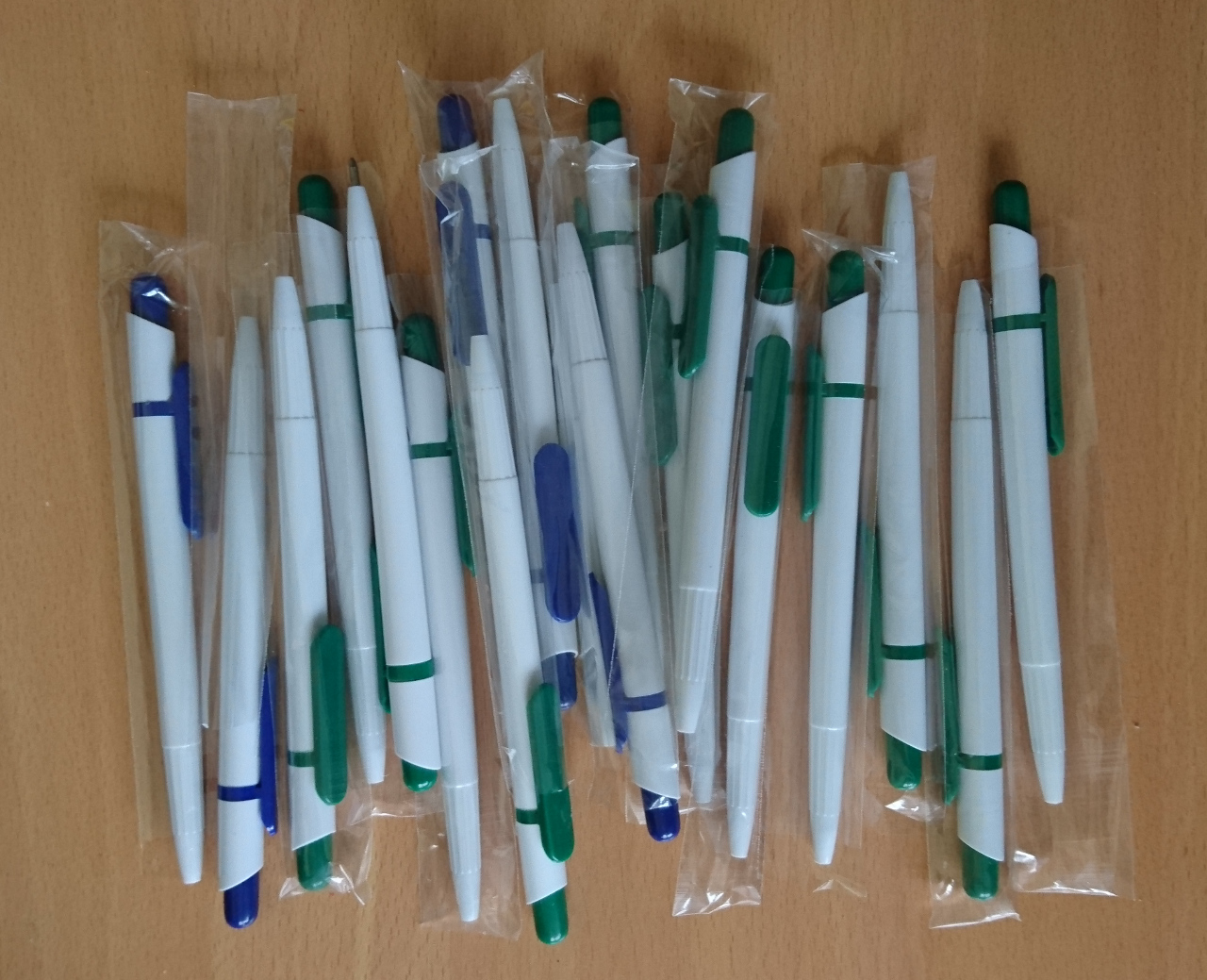
For brush to to tightly pushed against copper slip ring we needed springs. After some search on the internet, the cheapest option presented itself in quite an unlikely form (and quite wasteful form) - £3 worth of pens:

Serious Hardware

Now we can re-do the inner brushes:

Inner Brushes Re-done

And outer, too:

Outer Brush

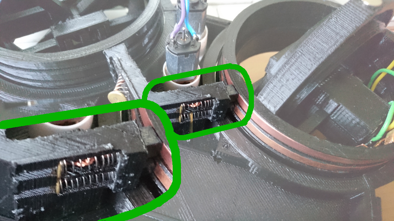
The outer brushes holder has two by two brushes - at the same time covers two opposite wheels. THe same thing helps us with amount of wires we need to handle between 'body' and 'top platform':

Brushes Wired

Here you can see three set of wires going to one side connector (two opposite inner brushes and one double brush holder). Also, you can see that we've added micro deans connectors to motors - so they can be easily attached to motor controllers. Aside of that there's XT60 connector that is there to connect bottom of the rover (brushes) and the rest of the rover (read: power source). More about wiring in the next post!

YPutting All Together


Putting All Together

Now it is time to continue with our build. The wheel hubs are done, the design for the main body is ready - it is time to put all together!

Top Platform

To start with here's the first version of 'top platform' design. At the level of main body we have bulky bearings encapsulating wheels, motors that steer wheels, brushes and space for battery. Also we need place for Raspberry Pi, steering motor controllers, DC-to-DC converter, sensors, i²c multiplexer and so many other smaller things. They all will be stored on that platform.

Body And Brushes

Now here is main body with main brushes and battery connector.

Next is to add bearings, wheel hubs, clamps to hold bearings and platform holders:

Wheels and Platform Holders

Now we can add steering motors and gears:

Steering Motors in BodyBottom and Gears

This is how complete body layer looks with connectors added for brushes:

Building Rover

And when everything is covered with 'top platform':

Building Rover

Steering Motors and Controllers

Stepper Motors Tiny geared motors used in the body for steering are as well "Plan B" motors. The original idea was to go with geared micro stepper motors but that caused a few issues: they weren't fast enough, they were strong enough and there was an issue if driven too fast - there wasn't a suitable feedback that motor didn't really move whole step as required. Too many little problems that were supposed to be fixed. The original idea was that wheels would have some 'starting point' a contact to denote particular position or tab to cut IR LED/IR Photo Diode setup similar to old fashion mice (there was a wheel with slots moving in the middle of such setup). Wheel would at the start up move to such position and after that counting steps we would be able to say exact position of the wheel. But, if stepper can miss a step - whole idea would fall through as wheel might end up being in completely wrong position to what system believes it is. So, AS5600 + simple DC motor is solution forward.
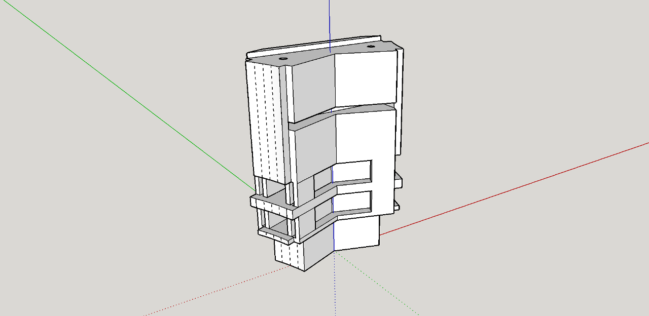
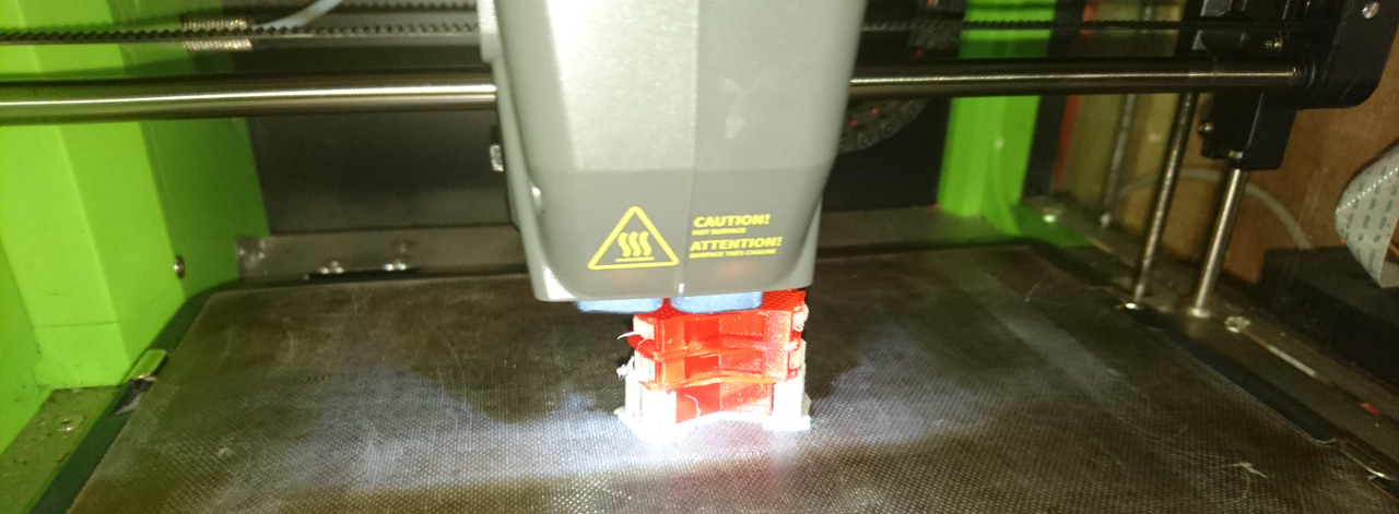
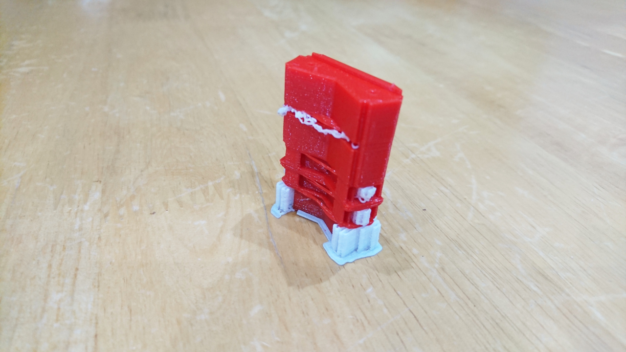
Now, we've got a few kind of micro geared DC motors for previous PiWars. Some marked as '150RPM', some '200RPM' and some '300RPM'. Others are marked as geared as 20:1 and 50:1 and both were geared 'faster' than 300RPM. All at 6V. The plan was to pick the fastest and make it turn the wheel. So, we started with 200RPM. Motors turned the wheels well @ 5V (we started with simple phone charger voltage) but not fast enough. Then we switched it to 50:1 geared motor and it couldn't turn it at all. It wasn't strong enough!

Over time we moved to battery's 8V (actually 9.4V from another AC/DC adapter first) and 200RPM motors performed adequately but was that the best we could do?

Then due to some unidentified issue one geared motor got stuck and brew motor controller (H bridge)! That prompted software change - if wheel doesn't reach required position for couple of seconds, it would be switched off for another couple of seconds for H bridge to 'cool off'. At the same time tiny motor was replaced but replacement didn't behave as expected: occasionally it struggled with load! After closer inspection we saw it was 300RPM motor - and that sorted it: '200RPM' we have originally put are the fastest we can go with.

It seems that there are plenty of improvement pending in that area as well - provided we have time. The 'only' thing we need to do is to source slightly better, stronger and slightly faster motors to replace these tiny geared (to '200RPM' @ 6V) motors...

Y3D Printing, Materials and Support


3D Printing, Materials and Support

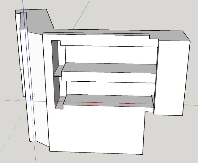
PiWars gave us opportunity to play with many different new technologies and learn new stuff. 3D printing was one of them. As our design get more complex they required more thinking and knowledge on how to produce good prints. In the previous blog Transferring Power To Wheels, Part II we talked about how orientation can help with avoiding support. But sometimes it is not as simple. A similar part again (for holding springs and brushes):

Spring Holder Design

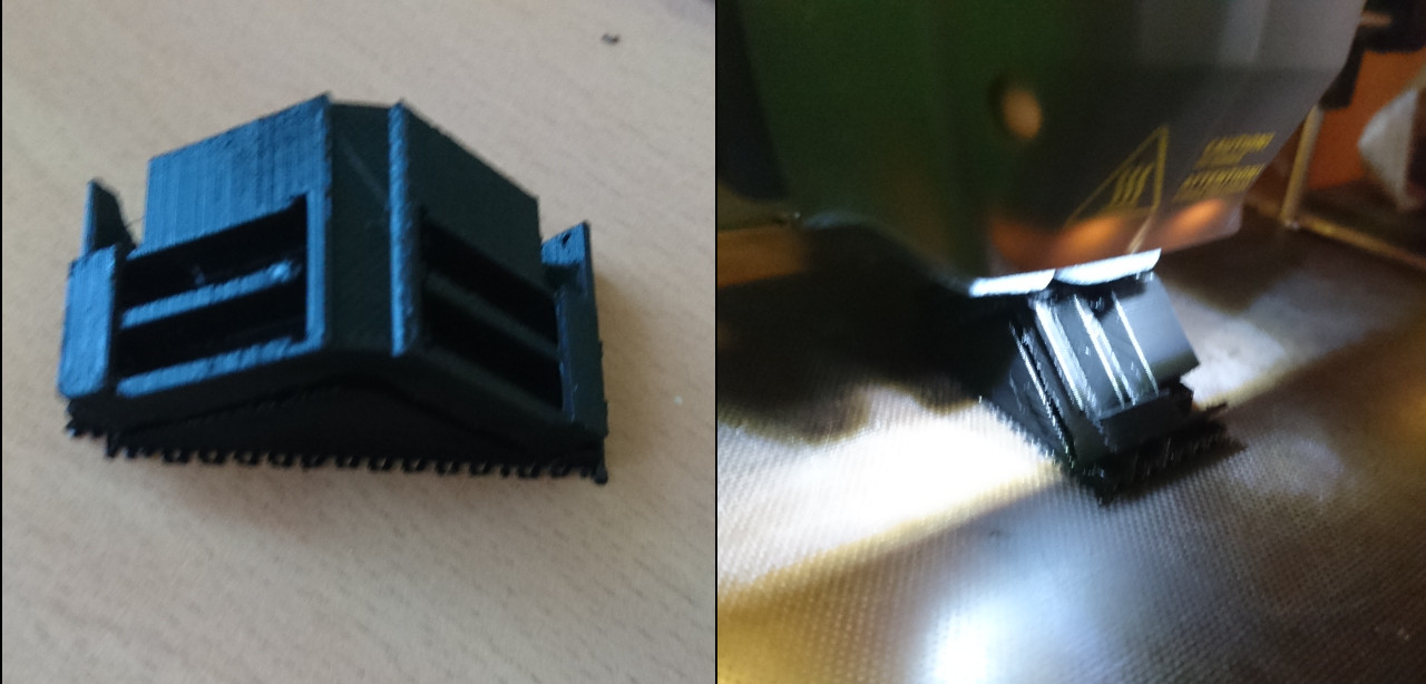
Now, we cannot turn it to some side and still achieve a similar quality of print like in the previous article nor avoid support inside of the cavities of that model. But luckily my previous visit to theTCT show at NEC got me nice sample of water soluble support material: BVOH by Fillamentum Industrial. And this was ideal opportunity to test is, especially as for printing with such support you need at least a dual head printer (which my CEL Robox is).

Printing With Support

It was left for Cura (the slicer underneath of Automaker - Robox's software) to decide where and how to add support:

Print With SupportPrint With Support

And when print was done all that was needed was to dunk a part of it into cold water for support to start coming off:

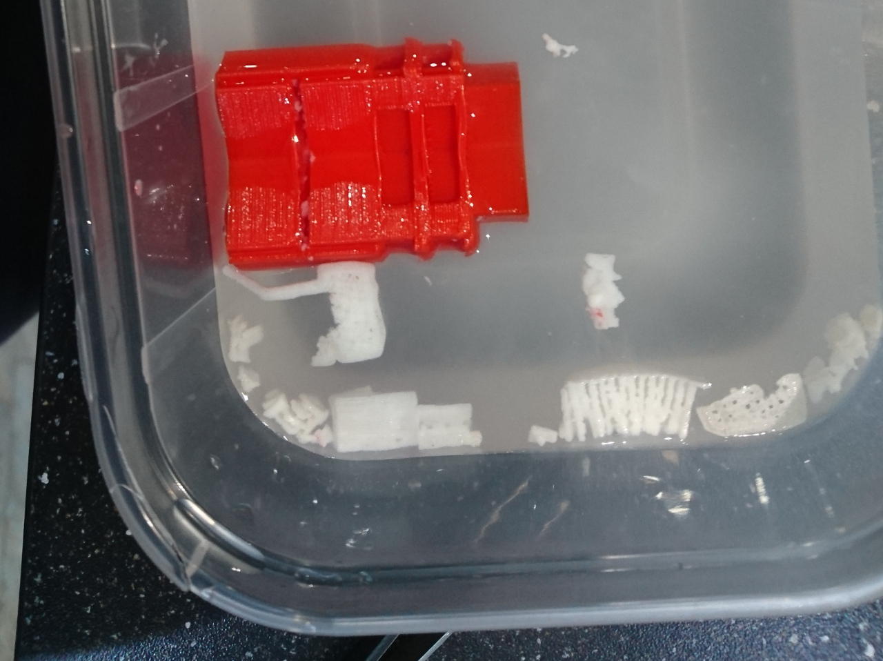
Support in Bath

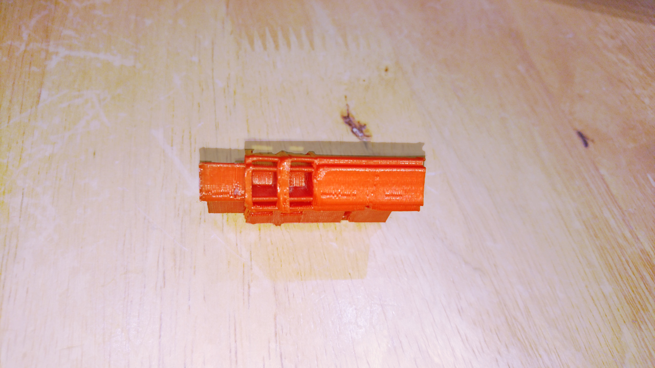
Cleaning after that was very easy as tiny pieces of support that remained on the part was so soft and easy to be pulled off with pair of pliers. If/where it stayed ever so slightly stubborn, some water helped it a lot. So the final part (especially cavities) came nice and clean:

Support Cleaned

That is really helpful especially for smaller parts where tolerances are lower than in bigger parts.

Epilogue

Sometimes a tiny bit of material stays just at the final entrance of a chamber that is heated in the printing head. It is usually very easy to be cleaned with tiny drill and if it still doesn't get out (after gentle rotating drill chopping the plastic) heating the drill's tip and re-inserting it would make plastic melt and be easy to pull out and stop obstructing the path.

But, it took several attempts with this material (cool down head after printing, take it off, heat tip of the drill bit, try to get final 1mm of material melt and stick to the drill tip, pull it out, mount head to the printer and try to get material through it) before the most obvious solution came to me: a few drops of water down the pipe that delivers filament to the chamber caused the material to degrade and stop obstructing path!

It turns out that this material, BVOH, is really easy to work with and seamless remove in water not leaving any residue on the print. Now I'll try to find a way to get more of it!

YLosing IMU Data


Losing IMU Data

Investigation and Solution

Introduction

This article discusses some of the problems I encountered whilst using a Raspberry Pi to read data from a complex sensor at approx 200Hz.

If you're short of time, just skip to the conclusions at the end of the article.

System Overview

The system contains an IMU (an LSM9DS1), a sensor which provides acceleration, angular rate and magnetic field measurements. The IMU has a "Data Ready" output pin. It sets the pin to 1 when new data is available and clears it when the data is read. There's also an API call which provides the same information. This "Data Ready" output is connected to a GPIO input on the Raspberry Pi.

The positioning system spawns a process to gather data samples. I call this a "Data Pump".

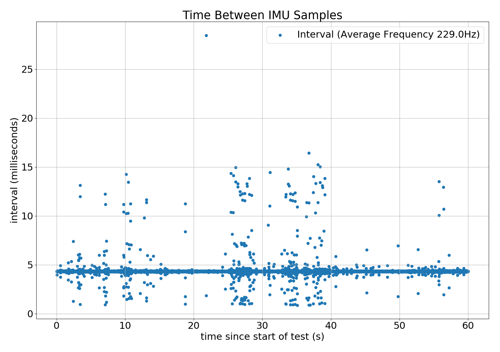
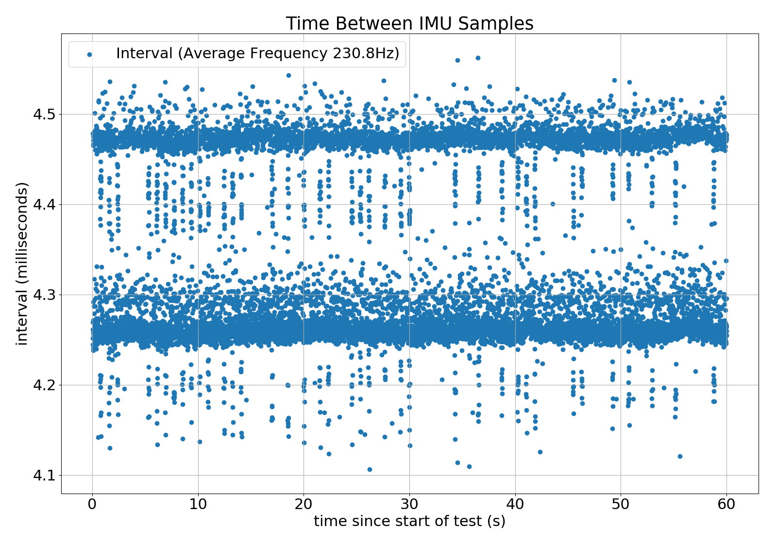
The IMU produces samples at 230.8 Hz. i.e. once every 4.3 milliseconds.

The Test

One of the first tests of my positioning system was to move the Pi backwards and forwards a couple of times. Each movement was about 1 metre and it accelerated at about 0.5g.

I recorded the raw IMU data as well as the output of the positioning system. I then spent the next month analysing the results and fixing things. I'd no idea that such a simple test could highlight so many issues! Most of these concerned the Madgwick algorithm I was using to determine the Pis attitude.

After I'd solved these problems I began to suspect that the data from the IMU was wrong in some way. It looked like the positive and negative accelerations didn't add up to zero even though the test started and ended with zero velocity.

Sample Data

Here's a few lines of the raw IMU data showing just the acceleration and gryo outputs while the Pi is stationary. Each row shows the sensor output at a point in time. The "dt" column shows the time between samples in milliseconds.

The IMU outputs are 16 bit signed integers. You can see this clearly in the acclerations for the z axis (Az). The full range of the accelerometer is 2g so 16384 represents 1g.

Sample Ax Ay Az Gx Gy Gz dt
1 -227 -149 16318 -6 -65 -127 2.30
2 -228 -150 16359 -13 -70 -128 6.94
3 -228 -150 16359 -13 -70 -128 2.33
4 -244 -147 16356 -3 -50 -125 2.51
5 -230 -139 16355 -14 -55 -121 6.94
6 -230 -139 16355 -8 -70 -119 2.34
7 -242 -154 16340 -2 -51 -114 6.92
8 -242 -154 16340 -2 -51 -114 2.30

If you look at lines 2 and 3 you can see that the data is identical. The same thing happens with lines 7 and 8. Given that these measurements are noisy it's vastly improbable that this happens at all, let alone twice in 8 samples. Those 8 lines are typical of the whole data set. In other words, at least 1/4 of my data points were invalid.

Analysis

At the time I gathered this data, the Data Pump was simply reading the IMU output at regular intervals. This was good enough for me to get going and allowed me to use someone else's driver.

When I wrote it, the polling interval was very predictable. If you look at the dt column you can clearly see it's not very predictable in this case. In fact, the interval between samples seems to be flip-flopping between a long and a short interval. In each case where there are duplicate rows, the interval between first and second row is a short interval. This happens because the IMU hasn't managed to gather a new sample before the Data Pump reads the data again. In this case it simply hands over the previous value.

If you compare lines 5 and 6 you can see a slightly different problem. The acceleration values are identical but the gyro values are different. With this IMU the accelerometer and gyro values are always captured at the same time. So what happened? The answer is that the IMU produced a new sample just after the Data Pump read the accelerations and just before it read the gyro. It got half of one sample and half of another.

There's actually an even more insidious variation of this problem. The IMU doesn't set the high and low bytes of each value at the same time. It's possible to read a value with the high byte from one sample and the low byte from a different one. This tends to show up as a value that approximate 250 points higher or lower than expected.

To summarise, the underlying problem is that the Data Pump was reading data from the IMU without knowing whether a new sample was ready or not.

Using the Data Ready Pin

The obvious solution to these problems was to change the Data Pump to wait for the "Data Ready" signal and then read the data. As long as the Data Pump notices that data is ready and reads it within one cycle it will always get a new and self-consistent sample.

I connected the IMU's Data Ready pin to a GPIO (general purpose input/output) pin and used this GPIO code to wait for the pin to rise from 0 to 1.

return GPIO.input(self.gpio_pin) or GPIO.wait_for_edge(self.gpio_pin, GPIO.RISING, timeout=timeout)

This uses GPIO.input to see if the pin is already set. If not, it waits for the pin to go high.

I gave it whirl and checked the output from the IMU. The good news was that all the samples looked different. There were no more obvious duplicates.

One big surprise was the sample rate. According to the data sheet it should have 238 Hz. It actually came out at 229.9 Hz.

The time between samples looked better but not perfect. As you can see from this graph the time between samples was usually 4.3 milliseconds but was sometimes so high that the Data Pump must have lost samples.

alt text

For reasons I didn't understand at the time, the CPU load on the positioning system and Data Pump would often double. (I later discovered that this was caused by the Pi throttling the CPU when it detected a low voltage condition on the power input.) I also wanted to be able to record data and run diagnostics while the system was running without affecting it so I decided to stress the system by turning on all my diagnostics and logging. The results were not pretty!

alt text

If you check the scale you can see that in some cases it took more than 100 milliseconds to get a sample. In other words, the Data Pump must have lost about 20 samples. The scale of data loss is reflected in the average sample frequency which has dropped to 132 Hz. This is clearly not good enough.

Some Experiments

As you can imagine, I was a bit worried about these results. Clearly there was something wrong; possibly several somethings. I tried lots of experiments and established the following: the results were identical whether the Data Pump read the GPIO pin or called the API to get the Data Ready status there was no significant delay between detecting Data Ready and reading the data * if I increased the timeout while waiting for new data to several times the expected interval it would still time out occasionally

All this suggested that either the IMU wasn't setting the Data Ready status at regular intervals or GPIO.wait_for_edge wasn't detecting edges reliably.

At one point, I changed the call to GPIO.wait_for_edge to a tight loop that called the Data Ready API. That worked much better but meant that the Data Pump took 100% CPU. 100% CPU use isn't acceptable so I changed the implementation to sleep for a while between loops. All the problems came back. Gah!

After a bit of head scratching I came to the following conclusion: GPIO.wait_for_edge doesn't detect events reliably. My suspicion is that it usually works as long as the calling process is scheduled and doesn't work if the Linux process scheduler de-schedules it to let something else run for a while.

Final Code

In the end I made 2 changes to the code. First of all, I dropped GPIO.wait_for_edge and reverted to polling GPIO.input instead.

def wait_for(self, timeout: int) -> bool:
    """
    Returns true if when the pin transitions from low to high.
    Assumes some other process will reset the pin to low.
    :param timeout: time to wait for the interrupt in milliseconds
    :return: True if the interrupt happened. False if it timed out.
    """
    ready = False
    sleep_time = (timeout / 1000.0) / 30
    stop_time = time.monotonic_ns() + (timeout * 1000_000.0)
    while not ready and time.monotonic_ns() < stop_time:
        ready = GPIO.input(self.gpio_pin)
        time.sleep(sleep_time)
    return ready

I call this with timeout set to approx 1.5 times the expected delay. The factor of 30 means that the sleep time is approximate 1/20th of the total time to wait. This gives me an acceptable balance between CPU usage and timeliness.

This change isn't enough on its own as time.sleep() invites the Linux process scheduler to deschedule the Data Pump. This leads to periods of around 10 milliseconds when the Data Pump isn't running. The final fix is to make the Data Pump a high priority process. This tells the Linux process scheduler to return control to the Data Pump in preference to other processes.

    priority = os.sched_get_priority_max(os.SCHED_FIFO)
    param = os.sched_param(priority)
    os.sched_setscheduler(0, os.SCHED_FIFO, param)

As you can see from these results, I now get samples reliably and in a timely manner.

alt text

The average of these intervals is about 4.3 milliseconds as expected. The gap between the two dense lines across the graph is the equal to sleep time. i.e. it's the time between two polls. Polling more frequently would bring these lines together at the expense of more CPU load. I found that reducing the polling interval by a factor of 10 doubled the CPU time and reduced by the spread by a factor of 10.

The CPU load on the Data Pump is around 27% which is acceptable.

Conclusions

  • Many sensors provide some form of "Data Ready" indicator. You may get invalid or subtly incorrect data unless your system waits for Data Ready before reading the sensor.
  • GPIO.wait_for_edge() does not detect edges reliably. In some circumstances it misses some events completely.
  • A normal priority process cannot be relied on to events at frequencies over about 5 Hz.
  • The Raspberry Pi 3 B+ throttles the CPU when it detects low voltage from the power supply. This makes the CPU load appear to double.
  • Even though Raspian is not a real time operating system it can be made to sample data reliably at approx 200 Hz on a Raspberry B 3+. (At least under certain circumstances.)

Yi²c Multiplexer


i²c Multiplexer

For steering wheels we need 4 x AS5600 and, unfortunately, AS5600 only has one i²c address and it cannot be moved. So the only way to overcome this problem is to introduce an i²c multiplexer - a chip to allow splitting of i²c bus to many sub-buses. For this we chose PCA9545A, a 4 way multiplexer. But they don't make it in DIP packages as well and 24 pin adapter was in order, too.

But, 4 way multiplexer has quite a few wires, especially if we want to use each sub-bus several times. For instance, on each sub-bust we can put two VL53L1X with only one extra GPIO (to discriminate between two VL53L1X sensors in setup). That would mean that from this tiny chip we would need to draw 5 (GND, VCC, SDA, SCL, GPIO) x 3 (2 x VL53L1X and AS5600) x 4 (4 sub-buses) + another 5 (GND, VCC, SDA, SCL, GPIO - connection to main bus) lines. 64 in total! OK, we can omit 4 x GPIO to AS5600 but that's pretty much it. Here's what we did to alleviate situation:

Step 1

The first part of board is a 2 set of 3 i²c 'sockets' - each set for one sub-bus having two with 5 pins (GND, VCC, SDA, SCL and GPIO for VL53L1X) and one only four (GND, VCC, SDA and SCL - for AS5600). Also, middle one is directly on 'master' bus. Those two that have 5 pins, one of them is connected to GPIO and one isn't.

Step 2

Next is to add pull up resistors to SDA and SCL lines for each sub-bus. Then, replicate that little board one more time. After that we need to connect both sides together:

Step 3

To do so we used simple male pins to keep distance and electrically connect two opposite sides. GND, VCC and GPIO have to be connected together and only those pins are used.

Step 4

Finally - when all is put together we wired GND, VCC and GPIO lines towards the master bus (Raspberry Pi) and connect 4 sub-buses' SDA and SLC to the multiplexer, along with GND and VCC and add SDA and SLC connections to the master bus (Raspberry Pi's i²c)

Step 5

Now we have 4 sub-buses, each with 3 separate connections and pull up resistors. Also, we have two separate connectors on master bus. One will serve for 'further' expansions and another to connect pull up resistors for the master bus (right hand side on the picture).

YHub Controller


Hub Controller

Now we have sorted out getting power inside of wheel hub - next is to control the wheel. The wheel needs to know should it spin, which direction, which speed or if it should stop. Also, since we opted for AS5600 (12-bit Programmable Contactless Potentiometer) for a 'rotary encoder' we would like to have the position of each wheel reported back to the RPi.

For the brain behind the controller we have chosen ATmega328p - a well known µController used in Arduinos. Its responsibility here is to the control H bridge using PWM (using 8-bin Timer 0), read from AS5600 using i²c and listens requests from Raspberry Pi - controlling nRF24L01 using SPI interface.

Diagram

ATmega328

ATmega328p is a perfect little controller - it draws very little current, it is easy to program for and has enough support for peripherals we need: i²c, SPI, PWM and such. Original code I did in assembler (old - more than 20 years old habit), but after some thinking and introducing a PID algorithm into the picture we changed our mind and decided to go with something where float point arithmetics would be simply given. I've started with Artudino IDE stuff but there are so many little gotchas and pre-defined usage of a µController's resources that it didn't make much sense continuing with it. After a bit of help from Brian @ UsedBytes (thank you a lot for all the help) I've decided to go with slightly lower level AVR Libc. Interesting bit was that for 80% of the time trying to re-implement assembler code to C I was comparing result from compiler with my hand-crafted one and they were quite close. Only near the end when the functions started getting bigger and more convoluted, the compilers started introducing the stuff that compilers are for: storing intermediate results on stack, passing parameters through the stack and such and resulted assembler code stopped being as readable as it was at the beginning. Nevertheless - amount of 'excess' code needed for higher level coding is (finger in the air estimation after reading it) a round 20% to what it might have been if coded and optimised by humans - quite comfortable and acceptable. Especially for the comfort of using real variables, math operations, arrays, high level control structures (if/while/for) and such.

Power To Controller And Peripherals

The wheel hubs are powered directly from a LiPo battery at around 8V. The controller and peripherals (AS5600 and nRF24L01) require 3V3 so next to µController we need a voltage regulator. Fortunately all of them are really low current consumers so a tiny LE33C2 is more than sufficient. But, since we have sliding contacts - slip rings, power can actually fluctuate. To sort it out (in the short term) we used quite bulky capacitors - 470µF. Also, software is made to detect the µController 'browning out' and pass that information in the next status update (when its powered up again).

AS5600

SOIC to DIP Adapter It seems like a really nice and easy chip to communicate with and works 'out of the box'. First it needs a button sized magnet placed really close to it (see out wheel design), 4 wires connected to the µController (GND, VCC, SDA and SLC) and, what we learned hard way, DIR connected to GND or VCC to determine the 'direction' that the AS5600 will report. Doesn't matter what we select for the direction as we'll easily handle it in the calibration process on the Raspberry Pi.
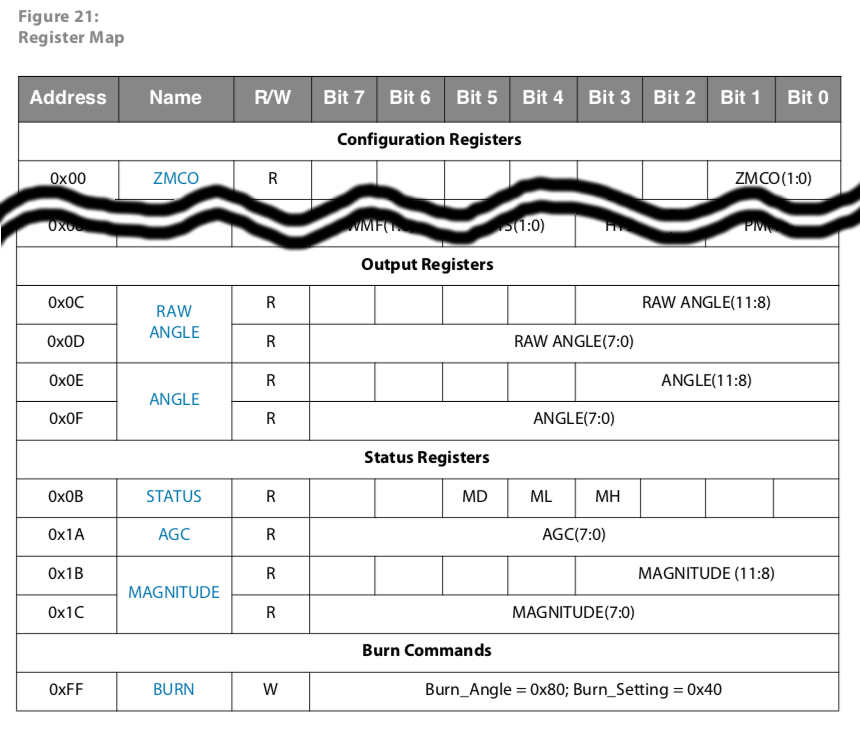
The next problem is that it is only produced in SOIC8 packaging - perfect for big numbers machined in PCBs - not so good for enthusiasts' projects. In order to make it more manageable we've first solder them to SIOC8 to DIP8 adapter

AS5600 Register Map

And, for software, all we need to do is to read the ANGLE and STATUS registers. Now, the STATUS register is at 0x0B address and angle at 0x0E address with 0x0C and 0x0D (RAW ANGLE) in between. It seems faster to read all from 0x0B to 0x0F (STATUS, RAW ANGLE and ANGLE) - 5 bytes or 7 in total reading/writing of i²c in comparison to two separate reads.

ANGLE is going to give us 12-bit (0-4095) absolute angle of the position of the wheel and µController is going to relay it back in it's response. Also, it can be internally used for PID controller for maintaining required speed.

nRF24L01

nRF24L01 is really nifty little transmitter that does quite a lot of heavy lifting in 2.4GHz spectrum range for us. Limitation is that it can only transfer packets up to 32 bytes long. Fortunately we don't need that much to convey all we need from Raspberry Pi to motor (mode to operate in, speed and maybe a few other bits and pieces) or from motor to Raspberry Pi (status, position of the wheel and such).

Bootloader

Also, there's extra benefit to it, too, secret weapon of a sort: in some of previous projects I've created small ATmega328p bootloader that works over nRF24L01 Now, it is really easy to program the ATmega328p (after it was originally flashed with that bootloader) - directly from Raspberry Pi. That bootloader checks one pin and if it is connected to ground it would go directly into the bootloader. If not it will proceed to the uploaded program.

Our wheels are powered through an unreliable power source we cannot rely that we'll be able to react and move µController to application as quickly as possible. So, bootloader pin has to be set to going to app immediately. So, the last 'ingredient' for the software for ATmega328p was special packet that would 'revert' code to bootloader - invoke bootloader from the application itself. The moment we do so, µController would slip back to bootloader mode and we would be able to upload new version of the software and reset it programmatically.

Production

And here we are again at 'production' stage - makings of 4 wheel hub controllers:

Wheel Controllers

As you can see there are plenty of tiny wires to be stripped, coated with tiny piece of solder and soldered at the right place. Here are µContoller, voltage regulator and nRF24L01:

Wheel Controllers

I've completely underestimated the amount of soldering needed for this task:

  • 4 x 2.4GHz radio with 8 wires flat cable => 16 times strip the cable, touch the end and 16 times solder each wire ==> 48 operations x 4 => 192 operations
  • 4 x 2 3 wire flat cables (one for power to µController and one for control lines) => 12 times strip, touch and solder => 36 operations x 4 => 144 operations
  • 4 x 2 wires for VCC and GND on the boards itself => 4 times strip, touch and solder =. 12 operations x 4 => 48 operations
  • 4 x 28 pin processor + 3 pin 3.3V regulator + 2x2 capacitors + one jumper between two GNDs = 36s solderings x 4 => 144 operations
  • 4 x 4 wires for magnetic sensor => 4 times strip, touch solder => 4 x4 = 16 operations
  • 4 x 2 pull up resistors => 16 soldering points

Total: 560 little operations... And some are SMD sized... Currently I think I'm half way through!

Here we have complete mess of all soldered: nRF24L01, H bridge - both soldered to µController's board along with big capacitor and pull-up resistors needed for i²c. Wheel Controllers

All that is needed now is soldering i²c lines (4 wires for AS5600), wheel hubs positive and negative terminal and tiny motor to H bridge's breakout board.

YAssembling Wheels


Assembling Wheels

Finally a pleasurable task: assembling rover wheels!

With all parts needed for one wheel hub printed...

All The Parts

... we can proceed with assembling the wheel hubs! Here are parts needed for one wheel hub along with tiny motor and AS5600 sensor on breakout board, along with printed wheel hub with copper rings:

Parts For One Wheel

First there's motor lid with the guard, second row shows motor holder and how motor is wedged in and on the last row we have completed motor holder.

Assembling Wheel Part 1

Now we can add the wheel to the motor shaft, and put the motor holder (without the lid) into wheel hub and then secure all with the lid.

Assembling Wheel Part 2

Next is to add bottom of holder for AS5600 sensor and secure it with a lid. Lid would keep that part of the hub secure and keep AS5600 in place.

Assembling Wheel Part 3

And finally - this is how rover now looks viewed from the bottom:

Rover

YBrushless Motor Torque


Brushless Motor Torque

Another setback. A perfect idea on paper but doesn't work in practice. Driving wheels directly from brushless motor seems to be no-go. Brushless motors are known to have really good torque, especially around 80-90% of their defined 'KV' rating. But at really low speeds power is not adequate for driving out a 1kg rover around.

At low speeds the motor is really acting as stepper motor (of a kind) and tiny windings which are more than adequate at speed defined by KV constant are not performing when just directly powered. Time for another Plan B: small geared DC brushed motors we used in previous rover. They nicely fit in side of the hub and can be driven by ready made H bridges based on TB6612FNG like this:

TB6612FNG

It is dual H bridge with theoretical constant current of 1.2A and peak allowed current at 3.2A. If both bridges are wired in parallel it might sustain even better current through it. And from previous years of PiWars we know that stall current of small geared DC brushed motors, driven at 2S LiPo battery (~8V) is around 800-900mA. So, it should be fine. Also, that breakout board nicely fits next to ATmega328p and nRF24L01 on one side of the wheel hub.

That, now prompted another design decision - a slight improvement of the wheel hub: if there is potential for motor to change through the course of R&D of this rover wouldn't it be better if we don't have to reprint the wheel hub every time we do so? Especially now the wheel hub is printed with capture copper rings? So, here it is - now the wheel hub can be disassembled to leave empty space and innards replaced with a newer, better version in the future. Hopefully near future! :)

New Wheel Huh

Next is to design wheel holder, motor holder, wheel guards, place for controller, etc...

YPower To Wheels, Part III


Transferring Power To Wheel, Part III

Copper rings around the plastic groove didn't work out - at least soldering a gap between two tabs slotted ends through the gap in the wheel hub. After a few consultations around, Richard suggested using copper wire instead!

Wires for Ring

The upper side is that 1.5mmm² wire is widely available (and it was so easy walking to shed and getting a few inches) and very easy winding it instead of copper strip. Downside is that barely 3 windings can fit 4.5mm groove and start and they have to be wound at some angle so start and end can fit. Also, they are not flat and on start and end places there was a bulge which affects brushes. At least it is a solution!


Dual Brushes

Brushes

Dual Brushes Again We've seen that carbon brushes do not work for us. Not with DC power we are trying to deliver to the wheel hub. So, here we go with alternative solution - using copper wire with some springs to mimic the action.
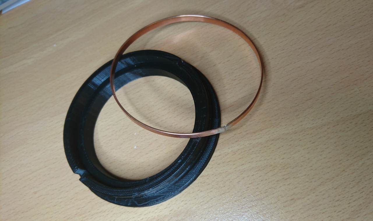
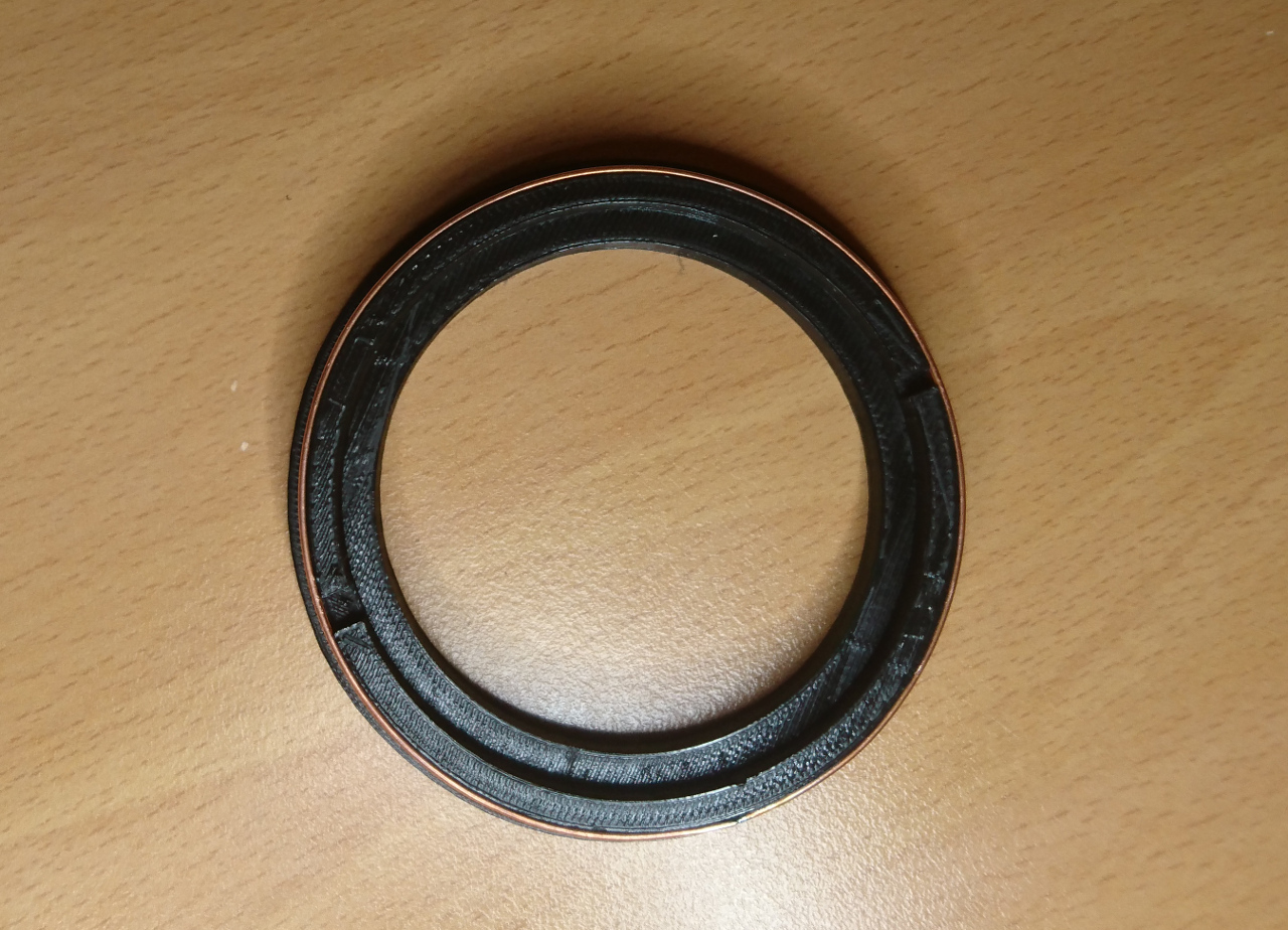
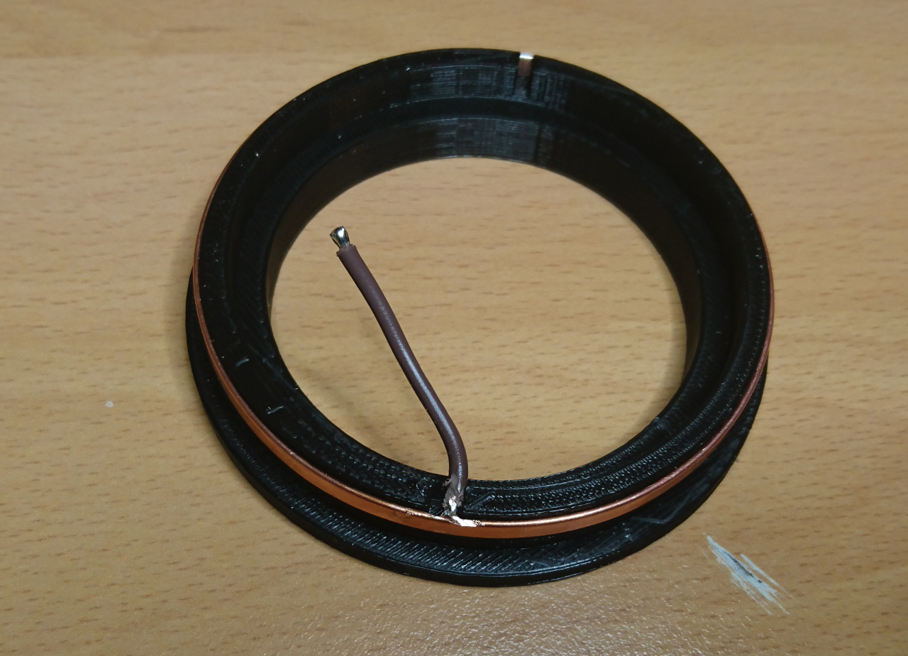
Why two brushes and not only one? Since wire rings do have bulges and dips, they are not entirely straight so if one brush 'misses', at least in theory, should still hold the contact. Also, instead of 1mm copper strip, which, generally speaking, is not flexible enough, we used 0.5mmm thick copper plate (cut to strips - fortunately ebay has a whole selection of different thickness and sizes). And as for springs? A few pens around the house suddenly become unusable... ;)

Unfortunately, even then wheel continued to have partial connectivity. Around 1/4 of the turn still didn't have appropriate contact.

Copper Rings

Ring And a Tool

Even though copper wires provided good enough connection they weren't ideal. A copper ring still has that kind of smoothness we would expect of slip ring. So, after a few sleepless nights (figuratively speaking) there was another idea that found it way out: why not make ring first, solder it and then (when cold) put it on wheel hub? To do so we devised new tool:

Ring ToolRing Tool

It is very similar to wheel hub's groove but without top side and with thicker walls for strength. It even has gap for a wire. Until original idea for copper ring to have tabs, this time we decided to make gap slightly wider and solder wire inside of the ring. So, process of making ring went as following:

Ring Tool

  • bend copper strip around the tool and cut it roughly to size having two sides overlap a bit
  • cut it more in small increments pressing it closer and more true against the circle of the tool until it cannot be stretched any more and gap between two ends is less than 0.5mm or so
  • take it off and solder the ends
  • cool it down in shallow bawl full of water (so we don't have to wait to continue working on it)
  • solder wire to inner side of the ring, away from the gap so it doesn't get undone
  • sand off excess solder from outside and inside of the ring
  • place it back on the tool (wire in the gap) and ensure it is as close to circle as possible (*)
  • make two rings with two differently coloured wires (positive and negative end)

Two Rings

Note (*) last few layers of the print before inserting ring might be still bit warm and hence soft and ring of some other shape might try to 'influence' the plastic.

Now printing hub is not as straight forward as it was before. Now we had to fetch gcode file produced for our printer, find right place and insert pause commands (M1). Simple way to find place in gcode is to use web site http://gcode.ws/. We just needed to find layer that is one below top 'lip' of each groove. Aside of M1 command for pausing printer, we added gcode commands to move the head away from the part:

G1 F12000 X10 Y145 Z535
M1

Printing is then done until first groove is finished, the ring is inserted with the wire going through the gap, then print continued until next groove is finished and then next ring inserted. So printing with a 'captured' ring looked like this:

Printing With Captured RingPrinting With Captured Ring

YPower To Wheels, Part II


Transferring Power To Wheels, Part II

When copper rings were in place all that was needed is to make gap between two sides of the ring filled in with solder, sanded smooth down and brushes added.

Of course, it is much easier said than done. And, as you'll soon see, not everything goes as planned (actually this project is riddled with such meandering paths)...

Brushes

Now we have slip rings we need to deliver power to the wheel - make contacts on the outside of the wheel hub. Original idea was to employ brushes for DC motors:

Carbon Brushes

We started with carbon brushes. They slot perfectly into the groove where copper ring sits, have own springs that keeps them pushed against the ring and can be easily and snugly fit to 3D printed holders:

Carbon Brushes

Little Digression

Brushes Holder

3D printing is a funny business. You can print whatever you want, but not really. As it is in FMD (Fuse Deposition Modeling) there are certain rules that must be followed. For instance - you can always extrude material if it can rest on something. You cannot just print in the thin air! Modern software that prepares 3D models for printing ('slicers') employ a few techniques that fix such situations - add 'support' material where it is needed. Only problem is that since we are talking about 'Fuse' technology, even though such programs deliberately leave certain gap between support and part of the object that is supported, it is never ideal and some material of the support stays attached to the main model. Also, if support is 'standing' on the existing object it is even harder to remove. With small parts like our brushes holder, left picture, the size of the support is proportionally much bigger in comparison to where it stays. In our case there would be gap where the brushes' spring goes. So, ideally we would like support to be used as little as possible. One way to achieve that is to find an appropriate orientation of the object we want to print so it can retain strength(*) and eliminate need for support (or just minimise it). In this case following orientation did the trick:

Brushes Holder Printing Orientation

Note: (*) in FMD 3D printing strength of printed objects, especially with small objects and objects with thin walls, lays along the extrusion lines - not between them

But...

But there was one little detail that was overlooked in this picture: carbon brushes are made of carbon, more or less similar substance resistors are made of! When measured, resistance of one brush (circuit from brush copper contact to copper ring through the brush) was in the region of about 20Ω . Two brushes twice the resistance. Result, given small metal geared DC motors is that voltage drop inside wheel was around 1/3! On 5V we tested everything, the voltage inside of the wheel was around 3.3V. When powered with 8V (2S) Lithium (LiPo) battery, wheel would get to only 5V. And that's not really enough. The current delivered is proportionally lower, too. So, that was another of the idea which didn't deliver solution as expected hoped for.

Copper Ring Gap

Copper Ring Gap 1Copper Ring Gap 2

As mentioned earlier the only part of the process that was left to finish our slip rings is soldering two ends and create smooth transition between to ends, tabs pushed through the gap to inside the wheel hub. But, we discovered, hard way, that temperature needed to solder wire to tabs is much greater than temperature needed to melt plastic (PLA in our case, but even ABS has quite a low temperature where plastic becomes soft). Also, even though copper is used to 'disperse' heat (in heat sinks for instance) it is at the same time quite good in conduction it!

Distorted Wheel Hub

YTransferring Power To Wheels


Transferring Power To Wheels

Slip Ring For wheels to turn (steer) 360º we cannot have wires going directly to motors and get twisted. Original idea was to go with a ready-made slip ring like this:
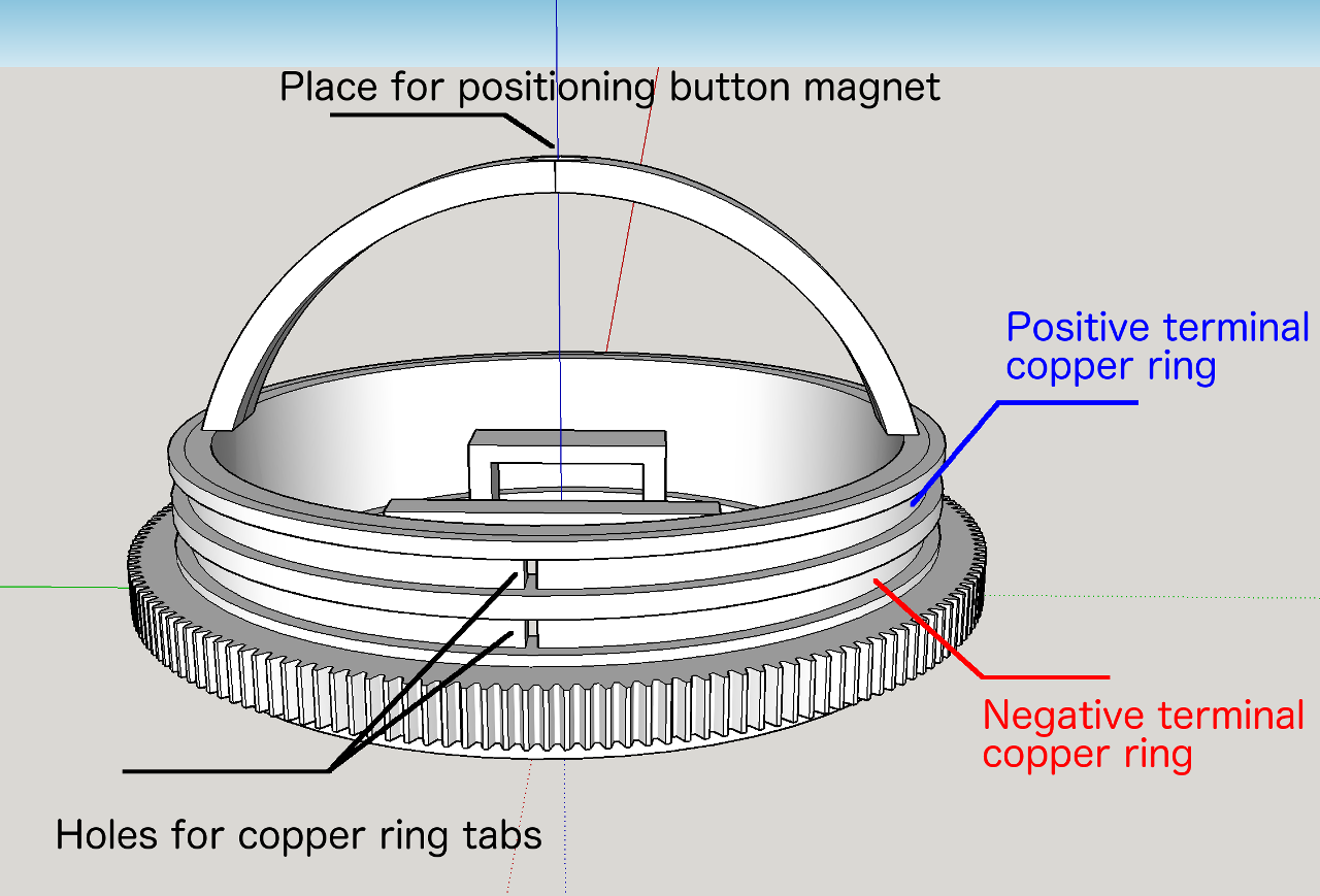
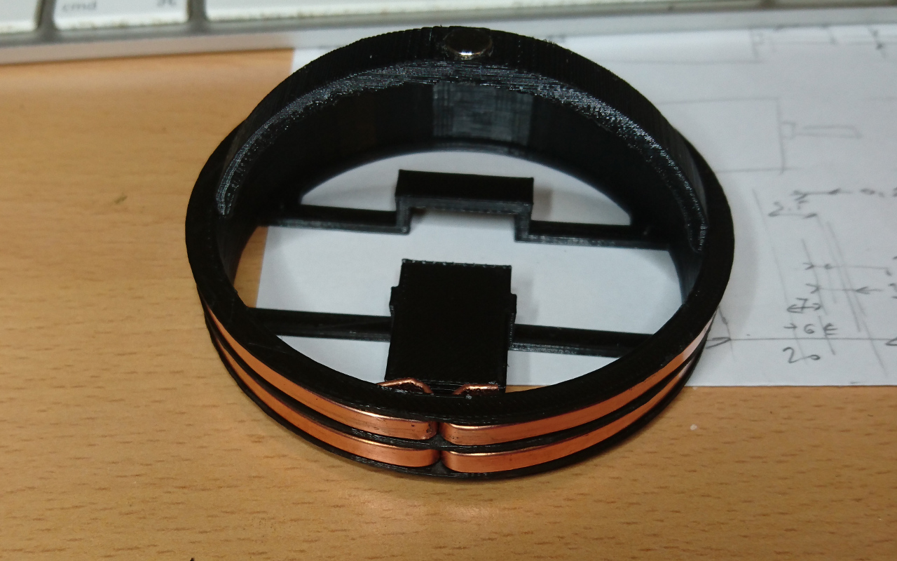
It has 6 independent wires were supposed to handle enough current with acceptable resistance but there was one snag: it would need to go directly at the 'Z' axis over the wheel. That wouldn't be an issue if we didn't plan to have absolute positioning which would use AS5600 (digital potentiometer) which requires tiny, button style magnet to occupy exactly the same place - the top of the wheel (wheel arch really) in the dead centre.

Alternatives

If we are not able to use ready made slip ring there are other options. One is to make our own or to try to pass power in contactlessly. Third option would be to not allow wheel go more than, let's say, 720º; count turns and 'rewind' back when needed. That would, after all, defeat idea of effortlessly steering with 360º freedom.

Rotary Transformer

A device that can allow that is called "Rotary Transformer" and is coming in one of two flavours: axial where windings sit inside each other and "pot core" where windings sit one on 'top' of another:

Pod And Axial Rotary Transformer

For such transformer to work we would need to make two coils, make DC to AC circuit and then add rectifier in the wheel hub as well. Not a small feat - especially for such a short time we have to sort out everything else for our rover...

More about that in this really nice master thesis of Mattia Tosi.

Slip Ring

So, the alternative is to make our own slip ring then. Since top of the wheel is taken for button magnet, we can position slip rings around the wheel - in same axis as main, big bearing is sitting. So, the plan is to make two copper strips that go around the wheel hub and use existing brush motor brushes to deliver plus and minus terminals of battery to inside of the wheel hub. We started with 3mm wide and 0.3mm thick slug repellent self adhesive tape. But, on the second thought 0.3mm thick tape is going to be quite thin and possibly rip on the excessive use. Next, slightly more robust solution is 4mm wide and 1mm thick copper plates ordered from the ebay. 1mm thickness is going to ensure life time endurance and Bosh brushes (the cheapest, smallest sold on the ebay again) are 4mm thick anyway so they seemed as a good match.

Design is like follow:

Wheel Hub Design

When printed it looks like this:

Printed Wheel Hub

Now, the internal tabs are going to be connected to motor controller (H bridge of some kind) for power and to voltage regulator for ATmega controller, nRF24L01 transceiver for communication to RPi and AS5600 as a wheel's "rotary encoder" sensor...

YBrushless Motor Controller


Brushless Motor Controller

Moving rover is the most important thing followed only by the ability to steer and control it. Our idea is to use gimbal brushless motors (like these) in the wheel hubs to the drive rover. Brushless motors are quite fast which helps a lot, but also the ones we selected are gimbal motors they are supposed to be able to move very precisely for minute changes in camera movements.

The idea was to start with something like BLheli programmable ESCs but the software inside of them wasn't good enough to drive them slowly. Normally drone ESCs (Electronic Speed Controllers) are made for fine control of speed when props are already rotating quite quickly.

So, the other option was to make a homebrew brushless controller like this: Spining BLDC(Gimbal) motors at super slooooooow speeds with Arduino and L6234. That particular article was the main inspiration - especially as ATmega chips with nRF24L01 were the original idea to sit in side of wheels and drive each wheel. Quite an exciting little side-project...

So, the controller is going to be the L6234 chip - three phase motor drivers with a 5A peak current through it. The original rover had four motors that each has a stall current at around 800-900mAh. With the rover that might now be twice the weight it shouldn't really go over twice that, so 5 amps seems quite sufficient.

Moving Motor

Brushless at club

To start with a homebrew brushless ESC we decided to use a Raspberry Pi for prototyping as setting up three PWM pins (and another three just for 'enable' of each phase) is dead easy. Our "prototyping" Pi was our "Pi on a stick" - a Raspberry Pi Zero with USB connector set up to work as ethernet device.

Pi Stick and Brushless Rig

The code to start with is really simple - all that is needed to move motor is to set one of three 'phases' to positive potential ('1') and other two to negative ('0') in H bridges:

#!/usr/bin/env python3
from time import sleep
import RPi.GPIO as GPIO

GPIO.setwarnings(False)
GPIO.setmode(GPIO.BCM)


GPIO.setup(17, GPIO.OUT)
GPIO.setup(27, GPIO.OUT)
GPIO.setup(22, GPIO.OUT)

o = GPIO.output

p = 0.2

while True:
        o(17, 0)
        o(22, 0)
        o(27, 1)
        sleep(p)

        o(17, 0)
        o(22, 1)
        o(27, 0)
        sleep(p)

        o(17, 1)
        o(22, 0)
        o(27, 0)
        sleep(p)

        p = p * 0.99

Moving Brushless Motor Slowly

Since our motor has 12 coils and 14 magnets (official designation 12N14P - "Common for higher torque applications. Noted commonly for its smooth and quiet operation." as per Wikipedia) that kind of program is not good for smooth operation. It would drive the motor 12 steps for whole circle - 30º per step. Since the wheels we'll have are going to be roughly 200mm in circumference, 12th part of it would be 16.6mm - quite a coarse movement. As per article mentioned above (Driving BLDC Slowly) we decided to use PWM and sinusoidal waves shifted 1/3 (120º in electricians' terms) apart. Sine waves were generated by open office's spreadsheet (as per article above) and embedded in code.

For instance:

PWM = [
[49, 93, 6], [50, 92, 6], [51, 92, 5], [52, 91, 5], [53, 91, 4], [54, 90, 4], [55, 90, 4], [55, 89, 3],
[56, 89, 3], [57, 88, 3], [58, 88, 2], [59, 87, 2], [60, 86, 2], [61, 86, 1], [61, 85, 1], [62, 85, 1],
[63, 84, 1], [64, 83, 1], [65, 83, 0], [66, 82, 0], [66, 81, 0], [67, 81, 0], [68, 80, 0], [69, 79, 0],
[70, 79, 0], [70, 78, 0], [71, 77, 0], [72, 77, 0], [73, 76, 0], [74, 75, 0], [74, 74, 0], [75, 74, 0],
[76, 73, 0], [77, 72, 0], [77, 71, 0], [78, 70, 0], [79, 70, 0], [79, 69, 0], [80, 68, 0], [81, 67, 0],
[81, 66, 0], [82, 66, 0], [83, 65, 0], [83, 64, 1], [84, 63, 1], [85, 62, 1], [85, 61, 1], [86, 61, 1],
[86, 60, 2], [87, 59, 2], [88, 58, 2], [88, 57, 3], [89, 56, 3], [89, 55, 3], [90, 55, 4], [90, 54, 4],
[91, 53, 4], [91, 52, 5], [92, 51, 5], [92, 50, 6], [93, 49, 6], [93, 48, 6], [93, 48, 7], [94, 47, 7],
[94, 46, 8], [95, 45, 8], [95, 44, 9], [95, 43, 9], [96, 42, 10], [96, 41, 10], [96, 41, 11], [97, 40, 12],
[97, 39, 12], [97, 38, 13], [97, 37, 13], [98, 36, 14], [98, 36, 15], [98, 35, 15], [98, 34, 16], [98, 33, 17],
[99, 32, 17], [99, 31, 18], [99, 31, 19], [99, 30, 19], [99, 29, 20], [99, 28, 21], [99, 27, 21], [99, 27, 22],
[99, 26, 23], [99, 25, 24], [99, 24, 24], [99, 24, 25], [99, 23, 26], [99, 22, 27], [99, 21, 27], [99, 21, 28],
[99, 20, 29], [99, 19, 30], [99, 19, 31], [99, 18, 31], [99, 17, 32], [98, 17, 33], [98, 16, 34], [98, 15, 35],
[98, 15, 36], [98, 14, 36], [97, 13, 37], [97, 13, 38], [97, 12, 39], [97, 12, 40], [96, 11, 41], [96, 10, 41],
[96, 10, 42], [95, 9, 43], [95, 9, 44], [95, 8, 45], [94, 8, 46], [94, 7, 47], [93, 7, 48], [93, 6, 48],
[93, 6, 49], [92, 6, 49], [92, 5, 50], [91, 5, 51], [91, 4, 52], [90, 4, 53], [90, 4, 54], [89, 3, 55],
[89, 3, 55], [88, 3, 56], [88, 2, 57], [87, 2, 58], [86, 2, 59], [86, 1, 60], [85, 1, 61], [85, 1, 61],
[84, 1, 62], [83, 1, 63], [83, 0, 64], [82, 0, 65], [81, 0, 66], [81, 0, 66], [80, 0, 67], [79, 0, 68],
[79, 0, 69], [78, 0, 70], [77, 0, 70], [77, 0, 71], [76, 0, 72], [75, 0, 73], [74, 0, 74], [74, 0, 74],
[73, 0, 75], [72, 0, 76], [71, 0, 77], [70, 0, 77], [70, 0, 78], [69, 0, 79], [68, 0, 79], [67, 0, 80],
[66, 0, 81], [66, 0, 81], [65, 0, 82], [64, 1, 83], [63, 1, 83], [62, 1, 84], [61, 1, 85], [61, 1, 85],
[60, 2, 86], [59, 2, 86], [58, 2, 87], [57, 3, 88], [56, 3, 88], [55, 3, 89], [55, 4, 89], [54, 4, 90],
[53, 4, 90], [52, 5, 91], [51, 5, 91], [50, 6, 92], [49, 6, 92], [48, 6, 93], [48, 7, 93], [47, 7, 93],
[46, 8, 94], [45, 8, 94], [44, 9, 95], [43, 9, 95], [42, 10, 95], [41, 10, 96], [41, 11, 96], [40, 12, 96],
[39, 12, 97], [38, 13, 97], [37, 13, 97], [36, 14, 97], [36, 15, 98], [35, 15, 98], [34, 16, 98], [33, 17, 98],
[32, 17, 98], [31, 18, 99], [31, 19, 99], [30, 19, 99], [29, 20, 99], [28, 21, 99], [27, 21, 99], [27, 22, 99],
[26, 23, 99], [25, 24, 99], [24, 24, 99], [24, 25, 99], [23, 26, 99], [22, 27, 99], [21, 27, 99], [21, 28, 99],
[20, 29, 99], [19, 30, 99], [19, 31, 99], [18, 31, 99], [17, 32, 99], [17, 33, 99], [16, 34, 98], [15, 35, 98],
[15, 36, 98], [14, 36, 98], [13, 37, 98], [13, 38, 97], [12, 39, 97], [12, 40, 97], [11, 41, 97], [10, 41, 96],
[10, 42, 96], [9, 43, 96], [9, 44, 95], [8, 45, 95], [8, 46, 95], [7, 47, 94], [7, 48, 94], [6, 48, 93],
[6, 49, 93], [6, 49, 93], [5, 50, 92], [5, 51, 92], [4, 52, 91], [4, 53, 91], [4, 54, 90], [3, 55, 90],
[3, 55, 89], [3, 56, 89], [2, 57, 88], [2, 58, 88], [2, 59, 87], [1, 60, 86], [1, 61, 86], [1, 61, 85],
[1, 62, 85], [1, 63, 84], [0, 64, 83], [0, 65, 83], [0, 66, 82], [0, 66, 81], [0, 67, 81], [0, 68, 80],
[0, 69, 79], [0, 70, 79], [0, 70, 78], [0, 71, 77], [0, 72, 77], [0, 73, 76], [0, 74, 75], [0, 74, 74],
[0, 75, 74], [0, 76, 73], [0, 77, 72], [0, 77, 71], [0, 78, 70], [0, 79, 70], [0, 79, 69], [0, 80, 68],
[0, 81, 67], [0, 81, 66], [0, 82, 66], [1, 83, 65], [1, 83, 64], [1, 84, 63], [1, 85, 62], [1, 85, 61],
[2, 86, 61], [2, 86, 60], [2, 87, 59], [3, 88, 58], [3, 88, 57], [3, 89, 56], [4, 89, 55], [4, 90, 55],
[4, 90, 54], [5, 91, 53], [5, 91, 52], [6, 92, 51], [6, 92, 50], [6, 93, 49], [7, 93, 48], [7, 93, 48],
[8, 94, 47], [8, 94, 46], [9, 95, 45], [9, 95, 44], [10, 95, 43], [10, 96, 42], [11, 96, 41], [12, 96, 41],
[12, 97, 40], [13, 97, 39], [13, 97, 38], [14, 97, 37], [15, 98, 36], [15, 98, 36], [16, 98, 35], [17, 98, 34],
[17, 98, 33], [18, 99, 32], [19, 99, 31], [19, 99, 31], [20, 99, 30], [21, 99, 29], [21, 99, 28], [22, 99, 27],
[23, 99, 27], [24, 99, 26], [24, 99, 25], [25, 99, 24], [26, 99, 24], [27, 99, 23], [27, 99, 22], [28, 99, 21],
[29, 99, 21], [30, 99, 20], [31, 99, 19], [31, 99, 19], [32, 99, 18], [33, 99, 17], [34, 98, 17], [35, 98, 16],
[36, 98, 15], [36, 98, 15], [37, 98, 14], [38, 97, 13], [39, 97, 13], [40, 97, 12], [41, 97, 12], [41, 96, 11],
[42, 96, 10], [43, 96, 10], [44, 95, 9], [45, 95, 9], [46, 95, 8], [47, 94, 8], [48, 94, 7], [48, 93, 7],
[49, 93, 6]]

All that is needed now is to send PWM to three pins from 3 places from above array, three places that are 1/3 of array length apart. Here is how it looks like moving brushless motor smoothly:

Controller

ATmega328p pinout

For a controller that can fit in wheel hub we have chosen the ATmega328p - there are enough free pins to cover 6 pins needed for L6234, 6 for nRF24L01 (more about it later) and a few spare for ADC and such. Also, it has three timers (two 8bit and one 16bit) all with two PWM outputs. Two eight bit timers with their corresponding PWM outputs work perfectly in this situation. Remaining 16 bit timer can be, then, used for internal timing.

Controller on breadboard

Conclusion

That week or two was really interesting and we learnt a lot about 3 phase motors, about PWM on Raspberry Pi, finding out how to check speed of the motor by counting the number of frames on videos that it takes the motor to make one revolution and such.

Happy Crew at the Club

YGCC Rover M18 - The Design


GCC Rover M18 - The Design

PiWars

Great news! We have been accepted for PiWars 2019 and in nothing other than the Advanced category!

It seems that our ability to make unique designs and make a rover ready and on time for two competitions with (some) success in overall score brought us a place. There were over 150 applications and Mike and Tim (the organisers of the PiWars competition) had to pick 30-odd competitors for the first day (Schools and Clubs) and similar amount for the second day (Beginners, Intermediate and Advance category competitors). So, getting there wasn't a small feat!

The Design

This time we'll try to attempt something which nobody else did before. And it requires lots of engineering and programming effort. Also, this time we have extra members to help us with it.

Luckily, some of our existing code (and hardware) is at our disposal, so not everything has to be made from scratch.

It is going to be new, different, challenging... It might even deserve a code name this time (hey, team, wake up!)... But for now it is just a next rover, next generation rover or simple M18!

Design Goals

Here are new design goals:

  • 4 independently steerable wheels (4 is good number for stability)
  • Wheels must freely and continuously rotate 360º (or any number given battery life) in any direction.
  • Wheels should be able to 'steer' in about or, preferably, less than a second for 90º. Ideally no more a second for 180º.
  • Wheels should have absolute positioning on them.
  • Wheel steering should be absolutely positioned as well.
  • Wheels should be powered with, preferably brushless, motors that can drive wheels so rover moves at the rate of 3.5m/s.
  • Wheels should be able to move motors so rover can move with a resolution less than 1cm in each direction.
  • Ideally wheel motors should be able to accelerate rover at the rate of 3.5m/s²
  • 0.9g (9 m/s^2) acceleration would be nice too but maybe rather optimistic
  • Centre of gravity should be as low as possible - less than 40 degrees above the contact points of the wheels
  • It should have flashy lights.
  • It should have sound.
  • It should have a display for funny faces and serious commands and feedback.
  • It shouldn't have front and back and sides should be the same.
  • It should be able to track its position and orientation to precision of at least 1cm/1º in each direction at rate of 50 to 100 times a second.
  • It should accept direct commands over bluetooth (joystick/controller/gamepad) and UDP.
  • It should have at least rudimentary battery voltage measurement and preferably total current measurement. THat can be done by extra ATmega328p.
  • It would be really nice all power to the rover to go through 'power controlled' relay so it can be switched off completely programmatically.

Implementation Ideas

And here is how some of them can be done:

  • Four independent wheels of about 6.5m diameter (~20cm circumference)
  • Sitting in four hubs rotating on four as thin as possible bearings
  • Bearings that should handle both axial and radial load
  • Each wheel will have power delivered to it using copper strip and brushes
  • Each wheel driven by gimbal brushless motor
  • Each wheel motor driven by home built brushless controller
  • Each brushless controller driven by ATmega328p
  • Each ATmega328p should read of contactless potentiometer (magnetic)
  • Each ATmega328p should communicate wirelessly (2.4GHz) with main RPi
  • Each ATmega328p should be able to drive motor slowly and very quickly (see above) and transfers back pot info to the main RPi
  • Each wheel hub should be rotated with a brushed motor (steering motor)
  • Each wheel hub's steering motor should be driven by one channel of a dual H bridge (4 motors - two dual H bridges)
  • Each wheel hub should have magnet which is read by stationary contactless potentiometer
  • As four contactless potentiometers are needed and they are communicating with i²c interface on one fixed address there's a need of 4 way i²c multiplexer
  • Each side of the rover will have a distance sensor (preferably ToF)
  • Rover will have 9dof sensor (accelerometer, gyro and compass)
  • Rover will use any other possible means for determining precise location and orientation
  • If needed more than one Raspberry Pi will be networked together use USB: Raspberry Pi 3B (or 3B+) to be used as main and one or more Raspberry Pi Zeros in USB/Ethernet gadget mode
  • Rover is to be powered by 2S or 3S LiPo battery (of at least 1000mAh capacity - preferably 2000mAh or more)

Plan Bs

... and Cs and others...

More than one item above might not work. Here are some thoughts of Plan B scenarios:

  • If a gimbal brushless motor cannot deliver required speed then it can be replaced by 'ordinary' brushless motor. Or as plan C with brushed motor that fits wheel hub's envelope.
  • If copper strips and brushes do not work appropriate battery is to be sourced and placed inside of the hub (increasing its weight so speed of turning can be affected)
  • If small brushed motors cannot turn hub or turn it quickly enough they can be replaced with bigger brushed motors or appropriate brushless motors driven by brushless ESCs
  • If wheel brushless motor has to be replaced with brushed motor for inside of wheel hub, then homebrew brushless controller can be replaced with dual H bridge breakout board (where both 'channels' are connected together)
  • If ToF sensors are slow then they can be replaced with 'fast' ultrasonic sensors or supplemented by some. Extra board (ATmega328 again) should be used in that case

Software

Aside of existing Pyros software, there are some aspirations we would like to achieve in the code:

  • Ability to steer rover in any direction at any time
  • Ability to rotate rover over any arbitrary point in space around the rover including (0, 0) - rotating over its centre
  • Ability to accurately track its position given initial position and heading
  • Ability to plot its surroundings given distance sensors
  • Ability to 'record' positions and paths through the time
  • Ability to smartly (still miss unexpected obstacles) replay recorded route

New Rover Prototype

Conclusion

As you can see - it is very, very ambitious and even if we succeed in half of the points we will have quite a unique rover. So, let's start with the making!

YGCC PiWars 2018


GCC at PiWars 2018

First apologies for such a delayed post. All the stuff we had to put aside for PiWars took priority and this slowly fall behind. But here we are. The TeamOur pit

In short summary - we finished 6th, much lower than expected, but still it is good reflection of all our members' hard work. With such luck and errors in judgement we could end up being much further down the list. But, the most important thing - to have good time getting ready for PiWars and enjoyed the event itself hasn't been spoiled - on contrary. I am sure that day was equally great as last years and we'll try not to miss next. And hopefully we won't!

So, without further ado here's what we did on the day:

Rover On TurnTable

10:40 Pi Noon Round 1

PiNoon was first challenge and quite an unlucky one. Our 'test' L shaped pin holding rods were slightly lighter and shorter (2mm instead of 3mm wire and maybe 5cm lower if not more). Previous year we suffered from our rover being very short and others were able to 'sneak' behind it and pop our balloons reaching across our rover's body. To overcome that we've extended the holder for 20mm ahead and thus made it much harder for someone to reach across our rover.

Downside was that with heavier and taller balloon holder moved centre of gravity higher (to already too high) and more to the front. Sudden turns would make rover topple over.

Rover Toppling Over

Also, I think it is fair to say we were the first ones to pop our own balloons in th new course with big tower with spikes in the middle. It is sufficient to say it didn't go well for us. Nerves, spikes everywhere, toppling rover and we managed to lose to a much slower and more shy rover. Better luck next time Naeem!

11:10 Straight Line Speed Test

This was, unlike last time, supposed to be one of our best challenges. It was proven that it was challenge where we ended up last!

Getting Ready

From start it didn't look good. Our rover just swerved to the left - away from the sun. Yes, the course was in sunlight and that was though: VL53L0X sensors do not like direct sunlight and we were realy hit by it. But, then it continued to swerve to the left even when it went into part of the course that was in the shade. How bizarre. We soldered on and finished it with many, many penalties but at least gave our best.

Straight Line

On the last go only fix was to move sensors from 45º/45º to something like 20º/70º and only then it didn't hit the wall immediately. Almost like right sensor was constantly reporting much bigger distances than left. And telemetry wasn't really built up to the standard so we didn't get to see any values while attempting the challenge. That's probably the first lesson we need to learn from 2018 competition: more feedback!

11:45 Slightly Deranged Golf

That challenge did expose another problem we have gone to competition with: last minute commits to git might not work as expected! It was a frantic moment when David and Naeem took over as soon as we discovered that controller is not really acting as expected - not all functions of PS3 controller buttons do what we expected. In this instance - ball 'catcher' (or 'the claw' here) just didn't move. They, in a style of best Hollywood films took over and after 15 minutes of frantic coding, they commented out all the 'bad' code and fixed it for the challenge. They wouldn't be able to do anything similar had they didn't write the code in the first place. Luckily, all was fixed in due time and we proceeded to the challenge area...

But, the claw was spot on:

The Claw

David's code for controlling the catcher worked perfectly and we had really good results. Time spent on design sessions, three prototypes down and score! Well done guys! This challenge was exactly as we expected it to be: really good times in all three goes and the first place overall!

Interestingly enough another team next day had implemented our design for capturing golf ball and achieved equally good results (second place in pro category).

Golf

13:10 Somewhere Over The Rainbow

That was another challenge we put quite a lot of effort. From first sessions were we talked about idea how to start tackling the computer vision and identifying what other problems we need solve, through those adoptive circle searching algorithms for OpenCV, all way to finding correct algorithms for traversing arena given differnet combinations of coloured balls. All paid off and our rover did perform like expected on the day. Well, almost. We needed to do couple of 'restarts' (rescues?) were first 'search' for the corner ended up more to the left than expected. Almost like left sensor did report much bigger distance than it really was. Otherwise - all coloured balls were detected with precision and rest of traversing through corners went exactly as coded.

We even asked judges to give us different set of combinations of balls as we were confident that we could solve any combination. Going three times with exactly the same combination of colours seemed a waste of all the effort we did to recognise them correctly.

As we didn't get chance to fine tune PID algorithms that were supposed to make our rover rotate for exactly 45º, 90º, 135º and 180º - those turnings and similarly finding right distance from the wall were a bit slower than they could have been. That caused us to be only 2nd overall (of 9 teams that attempted it), but still very, very good result!

Interim - Technical Merit

Well, something went really wrong here. We are still stunned by decision that our rover is judged last after previous year's first place. And, our rover was, after all, one of very few that were designed from the first principles - not only four motors on a board with Raspberry Pi in the middle. Janina, David, Naeem, Alex and others really felt let down as it seemed that their design and coding efforts were not considered at all.

Interim - Artistic

Here we've got completely opposite situation from Technical Merit. Last minute David and Naeem decided that they can do something more to the overall 'unattractiveness' of our rover. They wend down really hard in effort to add at least one more feature to it before artistic merit judging is closed that they've lost track of time and we completely missed it! But, with some incredible luck, we ended up being 8th of 10 awarded places (sharing it with some other rovers) which wasn't earned at all. Only thing we can say is 'thank you' to judges who did judge our general artistic skills (or there lack of) in our absence!

14:15 Minimal Maze

Now - there's another challenge which we though we would ace, almost like we did it last time. Last time lack of knowledge of rules and lack of any help from judge lost us a few points - we could have rescued our rover and had more successful runs than we originally had. This time we were ready but at the same time confident that we wouldn't need it at all! Oh, how wrong we were...

After first two corder, which our rover nicely navigated exactly as coded for, it suddenly got 'glitch' and seen opening on the left (can anyone see the pattern here) where there wasn't one and, falsely supposed that we are at that part of the maze were we need to switch from following left wall to follow the right wall. Outcome? It tried to turn back and run for its life. Almost like saying: "I don't want to be in this maze any more".

Bad Rover, Go There!

First time we luckily 'rescued' it in the right way and it picked up where it left and successfully left the maze. Next two times it didn't. Overall we were last. Last of only 4 teams that attempted it in the first place, so it wasn't that bad for our overwall score, but quite embarrassing.

15:10 Duck Shoot

Similarly to the Golf Course, extra fixing of commands was needed, but this time it almost seemed as routine task.

Light Armoured Rover

The Duck Shoot was one of the challenges were were aware that there's some skills involved and some issues with our shooting mechanism (we run out of time to make it better). And targets were really small and not so easy to be knocked down. Servo wasn't the best mounting place and cannon was nervously jumping up and down. Unluckily we managed to have so many nerf darts that went next to the neck (1cm up or down and it would be a hit) or to the base of a duck (so it wouldn't be strong enough to knock it down).

Overall - another 'unlucky' challenge and we were 13th of 21 teams that gave it a go.

16:15 Obstacle Course

Obstacle Course

Obstacle Course Finish

Well, this challenge didn't go much better than others. Nerves again (David managed to have rover fall of elevated U section, again!), but of bad luck (one motor wire got unsoldered while going through pebbles) but overall we did attempt it and finish it. Three motors did drive rover quite well (and driver was able to quickly adopt to the new situation - after all our rover can drive forward equally well as backward or sideways). Overall we were 12th of 15 places.

Blogging

Blogging

Blogging did take at least 1/5th of our effort and did pay off to the extent. We were third of 12 teams that did blog and helped us in final scoring.

Quick Analysis, Or What Went Wrong

One phrase can easily summarise it: human factor. In 2017 PiWars we used one VL53L0X sensor. That sensor went through torture software wise. Unlike many other i2c devices this didn't have simple protocol but only 'referential implementation' written in C. One of the efforts we put in that time was to translate it to 'pure' Python and that caused first sensor we had to go through unscheduled calibration. Or mis-calibration. Result was some unreliable distances - slightly bigger than what really they were. To fix it, given lack of time, the easiest thing was to buy another.

Many can already suspect what goes next. For this competition we got two more (as the price of them went to 1/2 within a year), but when it came to solder it to small PCB to switch them using XSHUT line, new ones went in first. But second pair (old pair) got soldered to slightly better, improved PCB and much neater. So, even though first pair was used in most of our coding, second pair (old pair) ended up on the rover because it looked neater. Result? Well - the first VL53L0X (mis-calibrated one) ended up as left sensor and caused rover not to see correct distance on that side. And all three autonomous challenges depended on reading distances correctly. Well - we failed almost all (but Somewhere Over The Rainbow) due to left distance was always read incorrectly.

Neat But Not Good

PiNoon is just bad luck - there's absolutely no blame for pilot of the rover at the time, as is for the Duck Shoot challenge. Even if cannon was more stable we could end up with similar result. One of the thing was that I insisted of not increasing speed of the cannon so it doesn't get damaged (and since it was only one it would prevent us complete the challenge). Slightly faster, stronger hits might have helped but again there's no way of telling. Obstacle course nerves did affect it (unlike last time we blamed latency of WiFi) and we lost some precious time for rescue where we shouldn't have fallen down.

Results:

Straight Line

But, overall score shows that steady work and perseverance pays off even when things didn't go well. If we say that in our view we failed at least 3 or 4 challenges and still came 6th of 29 teams! That's really good result!

  • The Obstacle Course - 12th
  • Slightly Deranged Golf - 1st
  • Minimal Maze - 4th (last) of 4
  • Straight Line Speed Test - last!
  • The Duck Shoot - 13th of 21
  • Somewhere Over The Rainbow - 2nd of 9 teams
  • Technical Merit - last!
  • Artistic Merit - 8th of 10 places
  • Blogging - 3rd of 12 teams
  • Overall - 6th of 29!

Final Word

I would like to use opportunity here to thank to all team members for all the effort - it did pay out! Here we have to mention some that helped the team:

Straight Line

Alex who due to exams couldn't join us on the day but was responsible for many design decisions, training of our pilots and special rover stand design;

Mr Kovacs, a teacher from Kenilworth school who helped club through the year and was cheering us on the day;

Andrew who implemented sonic sensors breakout board (which due to lack of time we couldn't incorporate as secondary distance sensors) and contributing to already big code base for various challenges;

Chris who, similarly to Alex couldn't join us on the day, but was CAD designing our cannon - the shooting mechanism;

Dorian for being event manager on the day, keeping time and recording the event with this phone;

Ed and Nick for helping out with the club's day to day business of teaching games creation fundamentals and generally cheering for us;

Naeem's dad for sponsoring club and family for cheering us on the day;

Creative Sphere, Vectric and Black Pepper companies for sponsoring our club with bits and pieces needed for our rovers, T-shits for the event and 'special rover stand' (mugs)

Kenilworth School for allowing club to operate on their premises and lending us brilliant students

and last but not least Janina, Naeem and David for making PiWars worth doing, if nothing else just to learn about engineering and programming needed for the event like this

and everyone else who contributed to GCC PiWars 2018! Thank you again!