Power To Wheels, Part III
Transferring Power To Wheel, Part III
Copper rings around the plastic groove didn't work out - at least soldering a gap between two tabs slotted ends through the gap in the wheel hub. After a few consultations around, Richard suggested using copper wire instead!
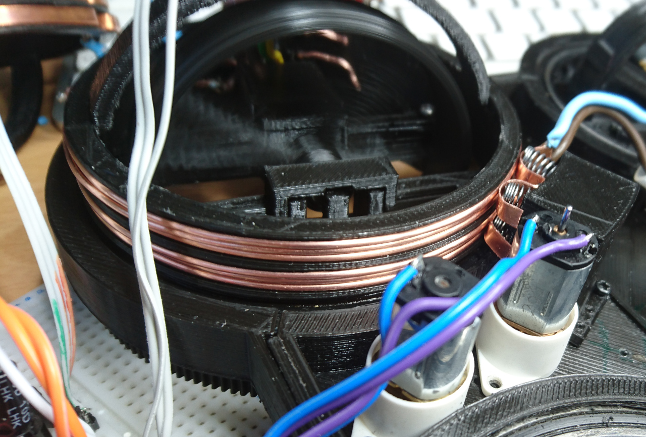
The upper side is that 1.5mmm² wire is widely available (and it was so easy walking to shed and getting a few inches) and very easy winding it instead of copper strip. Downside is that barely 3 windings can fit 4.5mm groove and start and they have to be wound at some angle so start and end can fit. Also, they are not flat and on start and end places there was a bulge which affects brushes. At least it is a solution!
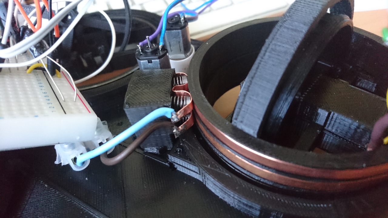
Brushes
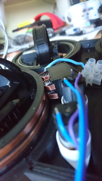 We've seen that carbon brushes do not work for us. Not with DC power we are trying to deliver to the wheel hub. So, here we go with alternative solution - using copper wire with some springs to mimic the action.
Why two brushes and not only one? Since wire rings do have bulges and dips, they are not entirely straight so if one brush 'misses', at least in theory, should still hold the contact. Also, instead of 1mm copper strip, which, generally speaking, is not flexible enough, we used 0.5mmm thick copper plate (cut to strips - fortunately ebay has a whole selection of different thickness and sizes). And as for springs? A few pens around the house suddenly become unusable... ;)
Unfortunately, even then wheel continued to have partial connectivity. Around 1/4 of the turn still didn't have appropriate contact.
Copper Rings
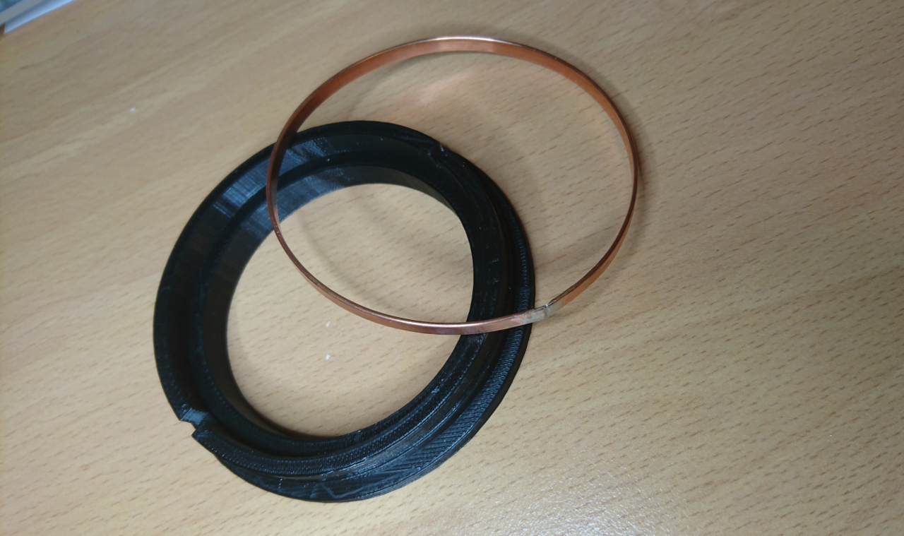
Even though copper wires provided good enough connection they weren't ideal. A copper ring still has that kind of smoothness we would expect of slip ring. So, after a few sleepless nights (figuratively speaking) there was another idea that found it way out: why not make ring first, solder it and then (when cold) put it on wheel hub? To do so we devised new tool:
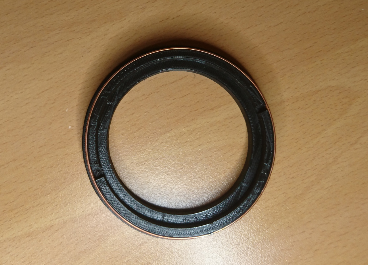
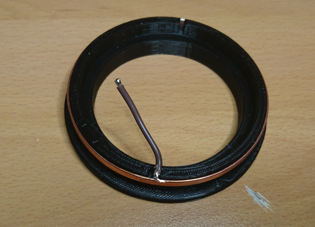
It is very similar to wheel hub's groove but without top side and with thicker walls for strength. It even has gap for a wire. Until original idea for copper ring to have tabs, this time we decided to make gap slightly wider and solder wire inside of the ring. So, process of making ring went as following:
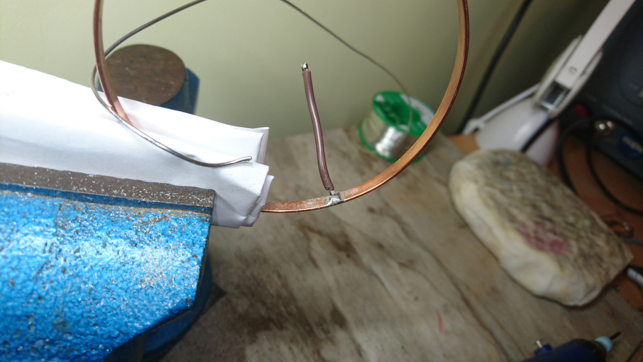
- bend copper strip around the tool and cut it roughly to size having two sides overlap a bit
- cut it more in small increments pressing it closer and more true against the circle of the tool until it cannot be stretched any more and gap between two ends is less than 0.5mm or so
- take it off and solder the ends
- cool it down in shallow bawl full of water (so we don't have to wait to continue working on it)
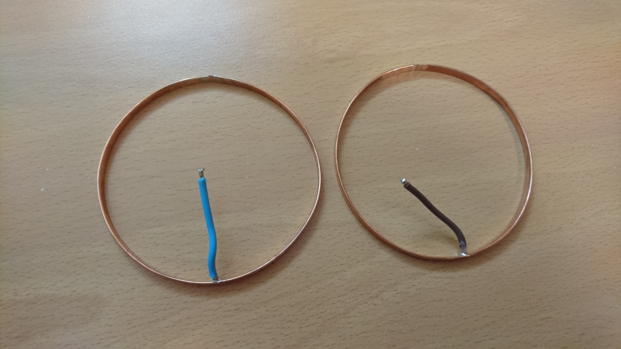
- solder wire to inner side of the ring, away from the gap so it doesn't get undone
- sand off excess solder from outside and inside of the ring
- place it back on the tool (wire in the gap) and ensure it is as close to circle as possible (*)
- make two rings with two differently coloured wires (positive and negative end)
| Note (*) last few layers of the print before inserting ring might be still bit warm and hence soft and ring of some other shape might try to 'influence' the plastic. |
Now printing hub is not as straight forward as it was before. Now we had to fetch gcode file produced for our printer, find right place and insert pause commands (M1). Simple way to find place in gcode is to use web site http://gcode.ws/. We just needed to find layer that is one below top 'lip' of each groove. Aside of M1 command for pausing printer, we added gcode commands to move the head away from the part:
G1 F12000 X10 Y145 Z535
M1
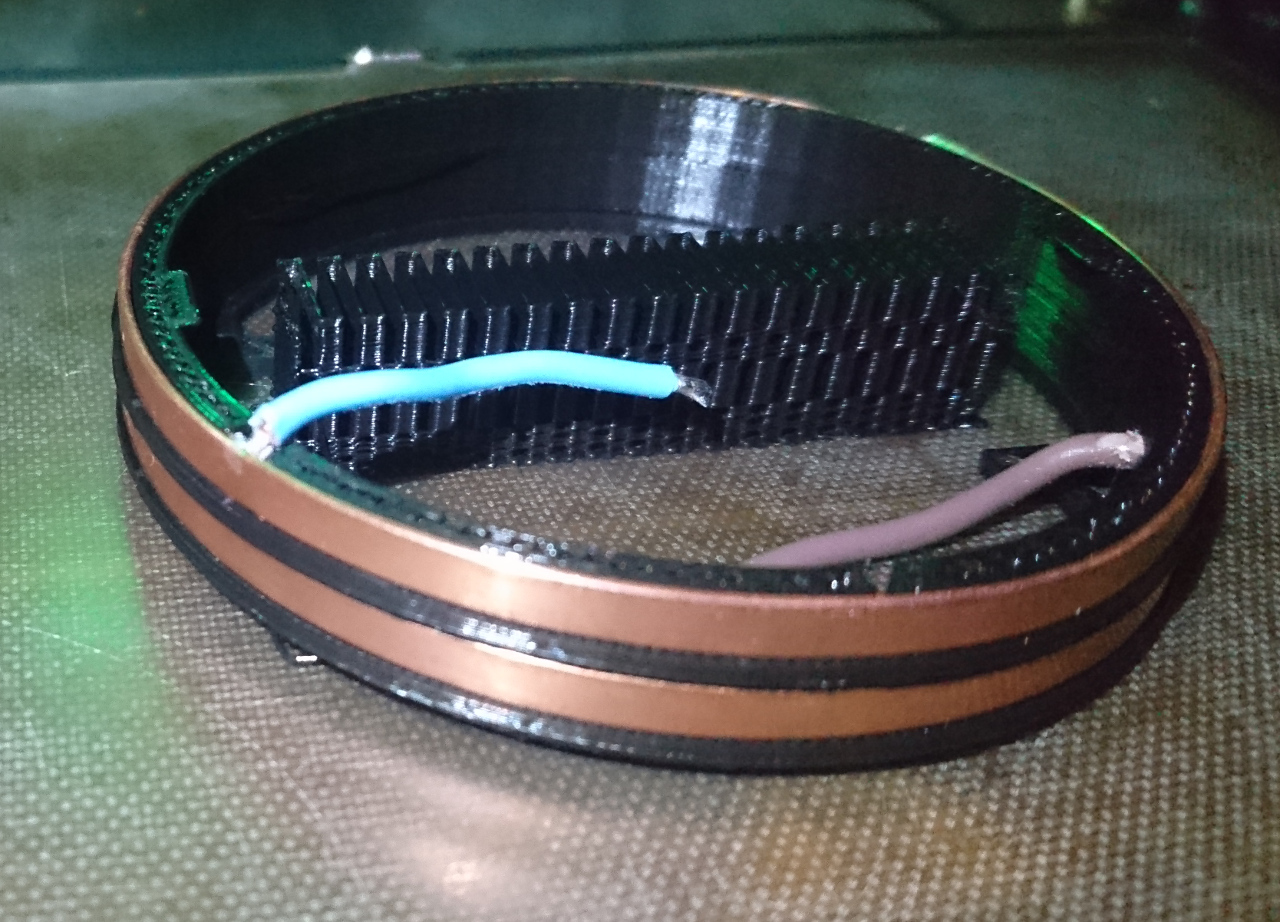
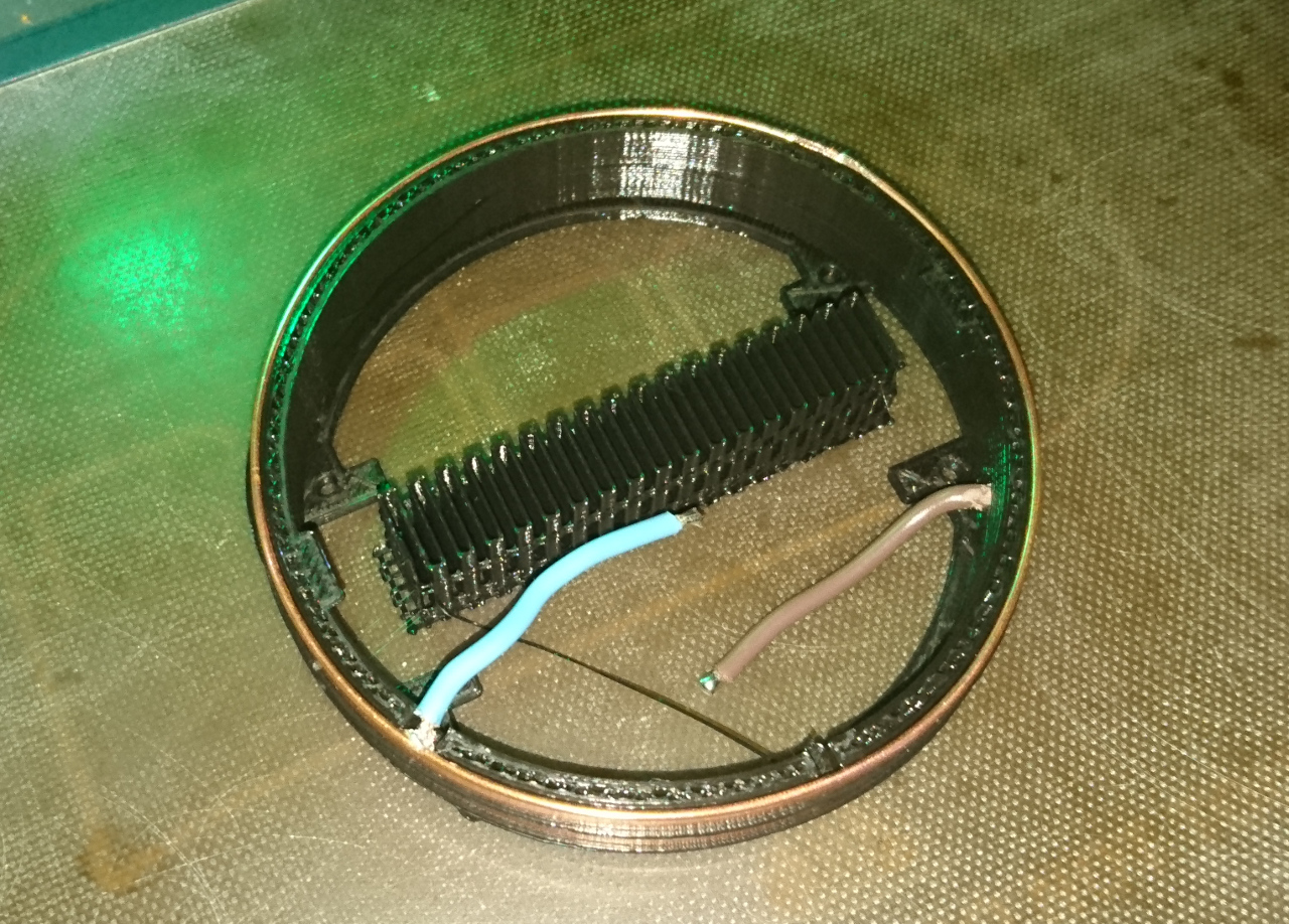
Printing is then done until first groove is finished, the ring is inserted with the wire going through the gap, then print continued until next groove is finished and then next ring inserted. So printing with a 'captured' ring looked like this:
Comments
Comments powered by Disqus