Posts about slip ring


YBrushless Motor Torque


Brushless Motor Torque

Another setback. A perfect idea on paper but doesn't work in practice. Driving wheels directly from brushless motor seems to be no-go. Brushless motors are known to have really good torque, especially around 80-90% of their defined 'KV' rating. But at really low speeds power is not adequate for driving out a 1kg rover around.

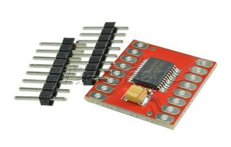
At low speeds the motor is really acting as stepper motor (of a kind) and tiny windings which are more than adequate at speed defined by KV constant are not performing when just directly powered. Time for another Plan B: small geared DC brushed motors we used in previous rover. They nicely fit in side of the hub and can be driven by ready made H bridges based on TB6612FNG like this:

TB6612FNG

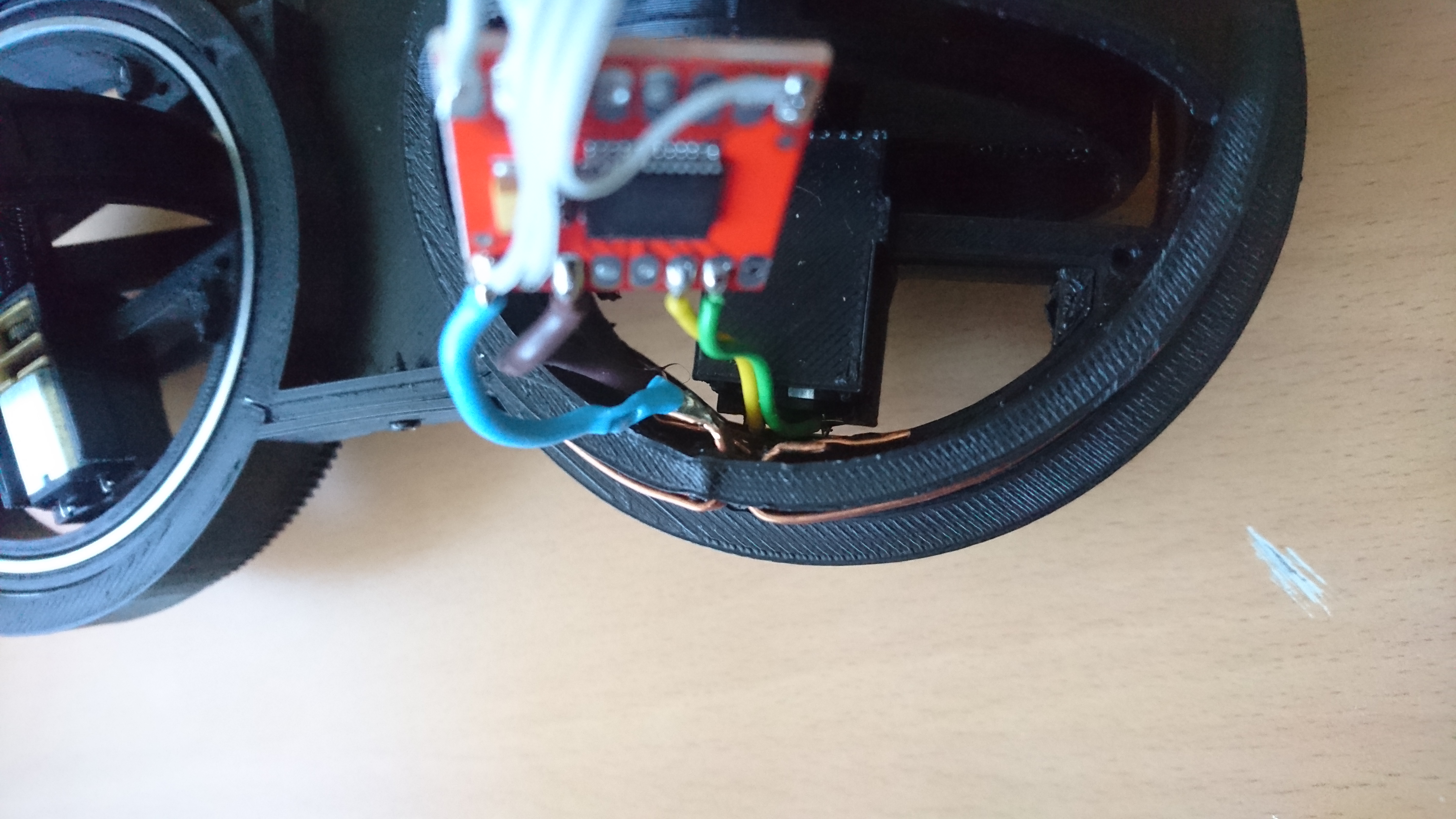
It is dual H bridge with theoretical constant current of 1.2A and peak allowed current at 3.2A. If both bridges are wired in parallel it might sustain even better current through it. And from previous years of PiWars we know that stall current of small geared DC brushed motors, driven at 2S LiPo battery (~8V) is around 800-900mA. So, it should be fine. Also, that breakout board nicely fits next to ATmega328p and nRF24L01 on one side of the wheel hub.

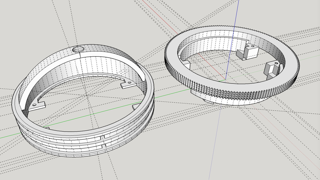
That, now prompted another design decision - a slight improvement of the wheel hub: if there is potential for motor to change through the course of R&D of this rover wouldn't it be better if we don't have to reprint the wheel hub every time we do so? Especially now the wheel hub is printed with capture copper rings? So, here it is - now the wheel hub can be disassembled to leave empty space and innards replaced with a newer, better version in the future. Hopefully near future! :)

New Wheel Huh

Next is to design wheel holder, motor holder, wheel guards, place for controller, etc...

YPower To Wheels, Part III


Transferring Power To Wheel, Part III

Copper rings around the plastic groove didn't work out - at least soldering a gap between two tabs slotted ends through the gap in the wheel hub. After a few consultations around, Richard suggested using copper wire instead!
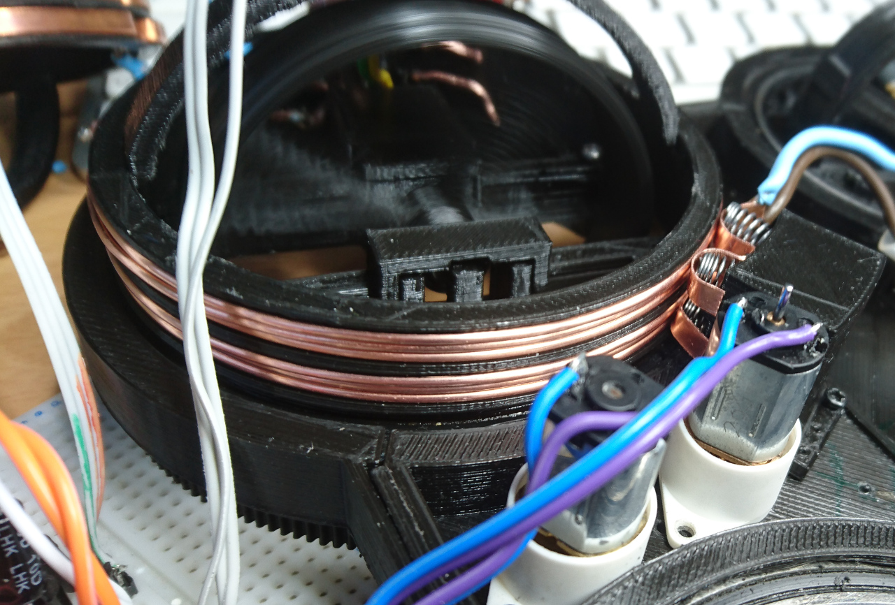
Wires for Ring

The upper side is that 1.5mmm² wire is widely available (and it was so easy walking to shed and getting a few inches) and very easy winding it instead of copper strip. Downside is that barely 3 windings can fit 4.5mm groove and start and they have to be wound at some angle so start and end can fit. Also, they are not flat and on start and end places there was a bulge which affects brushes. At least it is a solution!
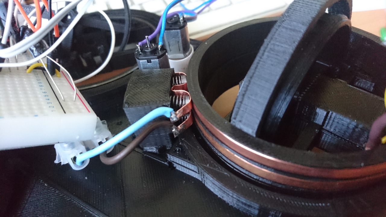

Dual Brushes

Brushes

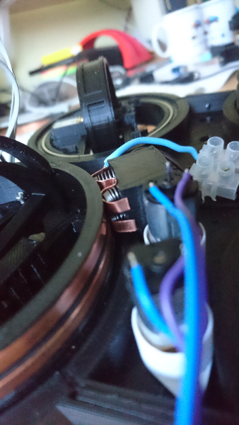
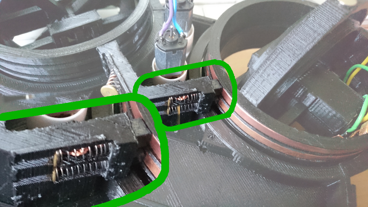
Dual Brushes Again We've seen that carbon brushes do not work for us. Not with DC power we are trying to deliver to the wheel hub. So, here we go with alternative solution - using copper wire with some springs to mimic the action.

Why two brushes and not only one? Since wire rings do have bulges and dips, they are not entirely straight so if one brush 'misses', at least in theory, should still hold the contact. Also, instead of 1mm copper strip, which, generally speaking, is not flexible enough, we used 0.5mmm thick copper plate (cut to strips - fortunately ebay has a whole selection of different thickness and sizes). And as for springs? A few pens around the house suddenly become unusable... ;)

Unfortunately, even then wheel continued to have partial connectivity. Around 1/4 of the turn still didn't have appropriate contact.

Copper Rings
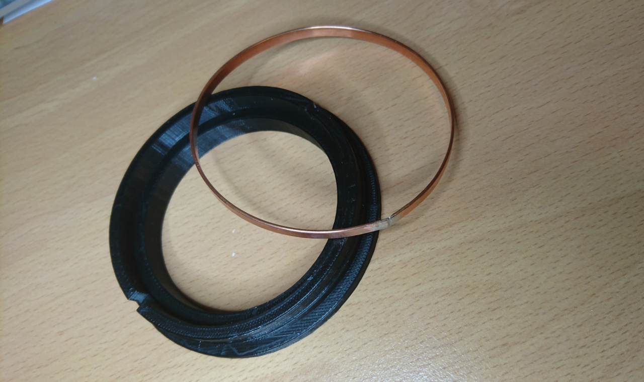
Ring And a Tool

Even though copper wires provided good enough connection they weren't ideal. A copper ring still has that kind of smoothness we would expect of slip ring. So, after a few sleepless nights (figuratively speaking) there was another idea that found it way out: why not make ring first, solder it and then (when cold) put it on wheel hub? To do so we devised new tool:
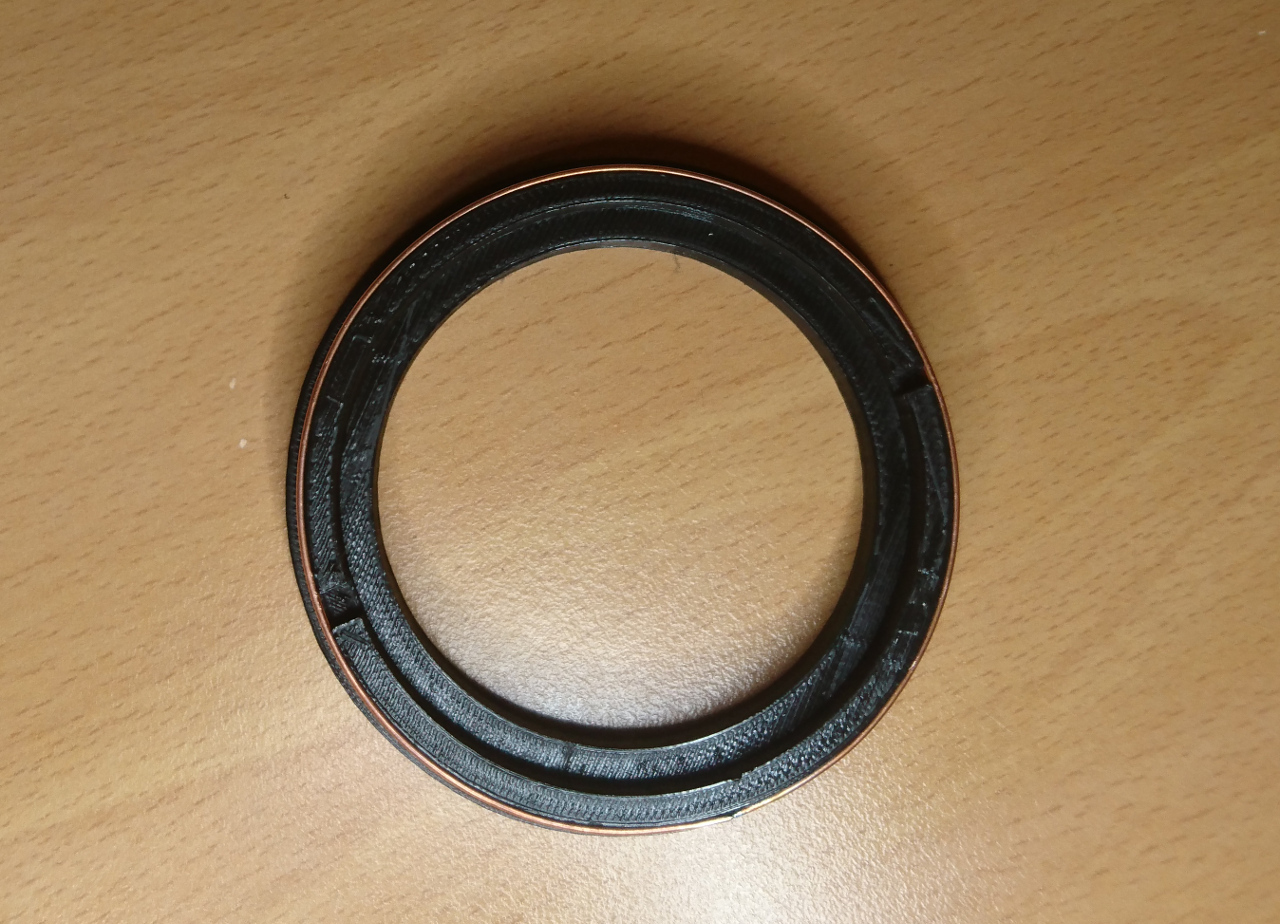
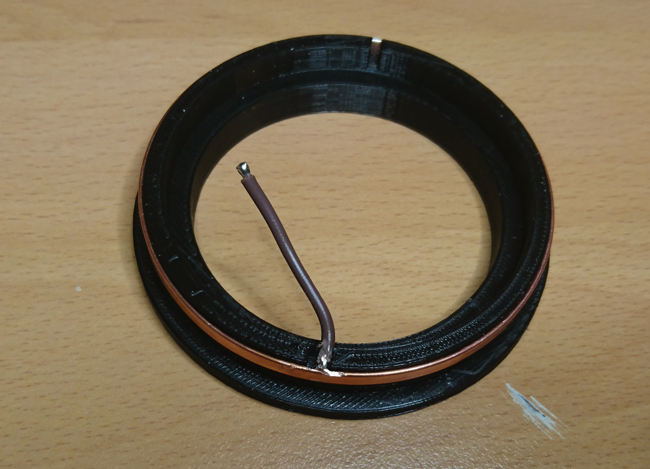
Ring ToolRing Tool

It is very similar to wheel hub's groove but without top side and with thicker walls for strength. It even has gap for a wire. Until original idea for copper ring to have tabs, this time we decided to make gap slightly wider and solder wire inside of the ring. So, process of making ring went as following:
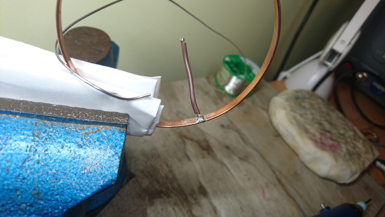
Ring Tool

  • bend copper strip around the tool and cut it roughly to size having two sides overlap a bit
  • cut it more in small increments pressing it closer and more true against the circle of the tool until it cannot be stretched any more and gap between two ends is less than 0.5mm or so
  • take it off and solder the ends
  • cool it down in shallow bawl full of water (so we don't have to wait to continue working on it)
  • solder wire to inner side of the ring, away from the gap so it doesn't get undone
  • sand off excess solder from outside and inside of the ring
  • place it back on the tool (wire in the gap) and ensure it is as close to circle as possible (*)
  • make two rings with two differently coloured wires (positive and negative end)
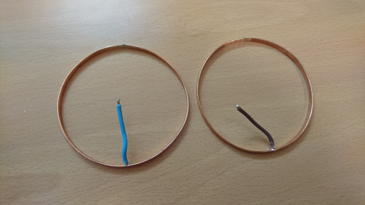
Two Rings

Note (*) last few layers of the print before inserting ring might be still bit warm and hence soft and ring of some other shape might try to 'influence' the plastic.

Now printing hub is not as straight forward as it was before. Now we had to fetch gcode file produced for our printer, find right place and insert pause commands (M1). Simple way to find place in gcode is to use web site http://gcode.ws/. We just needed to find layer that is one below top 'lip' of each groove. Aside of M1 command for pausing printer, we added gcode commands to move the head away from the part:

G1 F12000 X10 Y145 Z535
M1

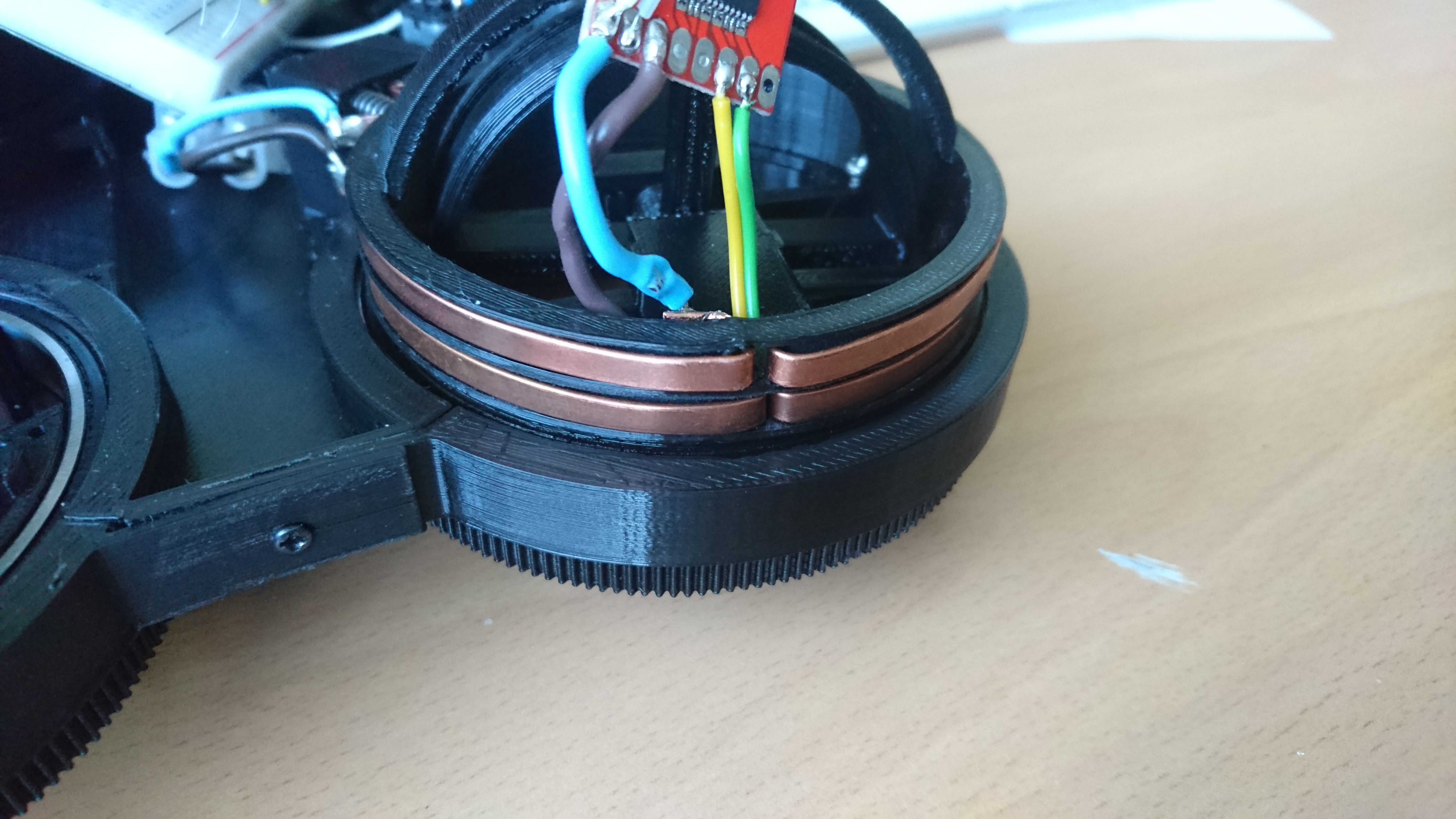
Printing is then done until first groove is finished, the ring is inserted with the wire going through the gap, then print continued until next groove is finished and then next ring inserted. So printing with a 'captured' ring looked like this:
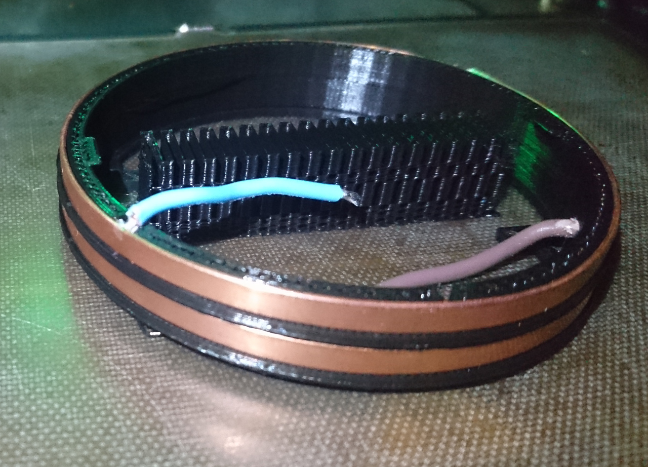
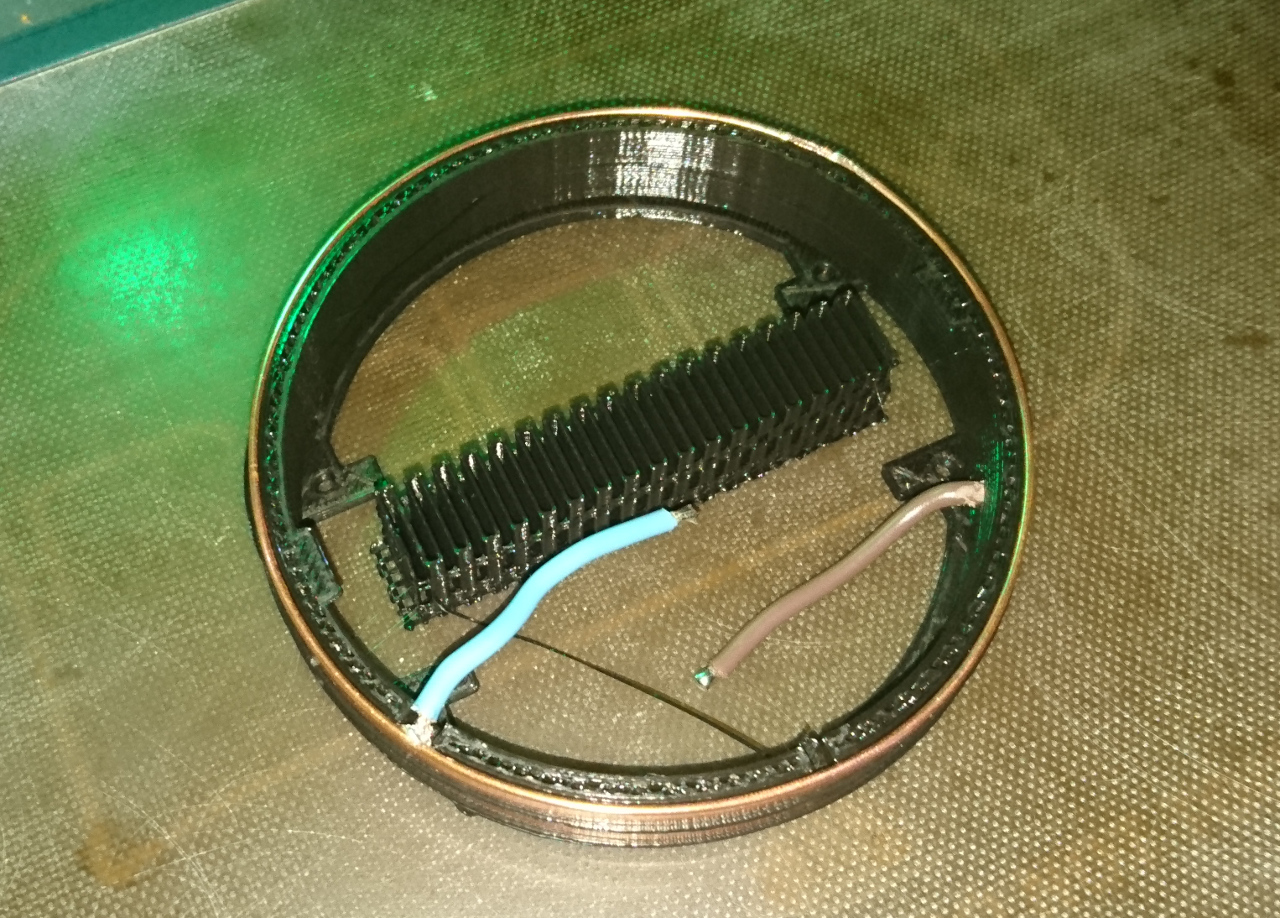
Printing With Captured RingPrinting With Captured Ring

YPower To Wheels, Part II


Transferring Power To Wheels, Part II

When copper rings were in place all that was needed is to make gap between two sides of the ring filled in with solder, sanded smooth down and brushes added.

Of course, it is much easier said than done. And, as you'll soon see, not everything goes as planned (actually this project is riddled with such meandering paths)...

Brushes

Now we have slip rings we need to deliver power to the wheel - make contacts on the outside of the wheel hub. Original idea was to employ brushes for DC motors:

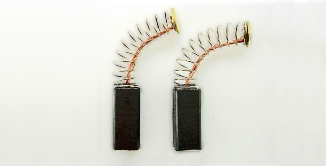
Carbon Brushes

We started with carbon brushes. They slot perfectly into the groove where copper ring sits, have own springs that keeps them pushed against the ring and can be easily and snugly fit to 3D printed holders:

Carbon Brushes

Little Digression

Brushes Holder

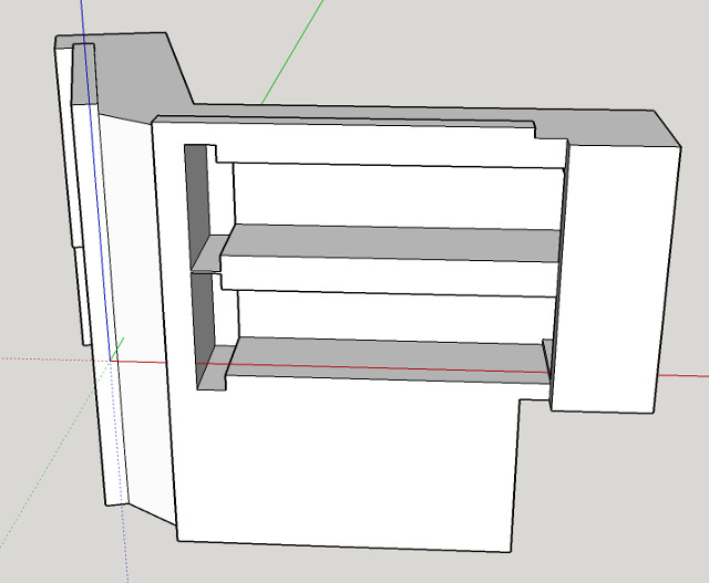
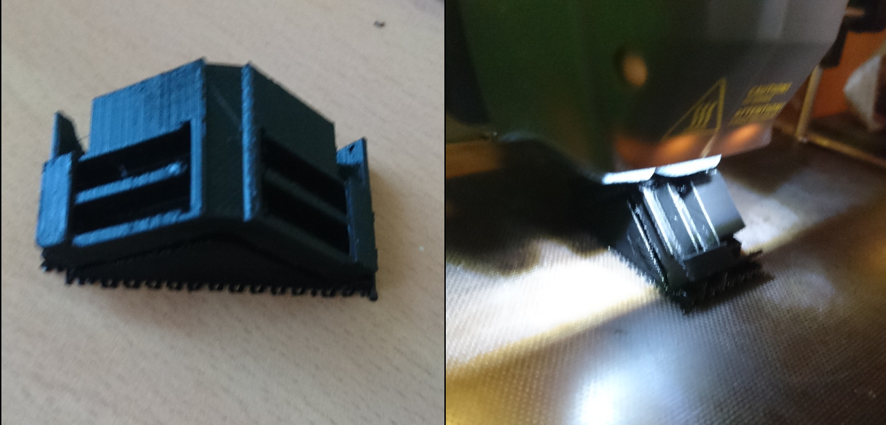
3D printing is a funny business. You can print whatever you want, but not really. As it is in FMD (Fuse Deposition Modeling) there are certain rules that must be followed. For instance - you can always extrude material if it can rest on something. You cannot just print in the thin air! Modern software that prepares 3D models for printing ('slicers') employ a few techniques that fix such situations - add 'support' material where it is needed. Only problem is that since we are talking about 'Fuse' technology, even though such programs deliberately leave certain gap between support and part of the object that is supported, it is never ideal and some material of the support stays attached to the main model. Also, if support is 'standing' on the existing object it is even harder to remove. With small parts like our brushes holder, left picture, the size of the support is proportionally much bigger in comparison to where it stays. In our case there would be gap where the brushes' spring goes. So, ideally we would like support to be used as little as possible. One way to achieve that is to find an appropriate orientation of the object we want to print so it can retain strength(*) and eliminate need for support (or just minimise it). In this case following orientation did the trick:

Brushes Holder Printing Orientation

Note: (*) in FMD 3D printing strength of printed objects, especially with small objects and objects with thin walls, lays along the extrusion lines - not between them

But...

But there was one little detail that was overlooked in this picture: carbon brushes are made of carbon, more or less similar substance resistors are made of! When measured, resistance of one brush (circuit from brush copper contact to copper ring through the brush) was in the region of about 20Ω . Two brushes twice the resistance. Result, given small metal geared DC motors is that voltage drop inside wheel was around 1/3! On 5V we tested everything, the voltage inside of the wheel was around 3.3V. When powered with 8V (2S) Lithium (LiPo) battery, wheel would get to only 5V. And that's not really enough. The current delivered is proportionally lower, too. So, that was another of the idea which didn't deliver solution as expected hoped for.

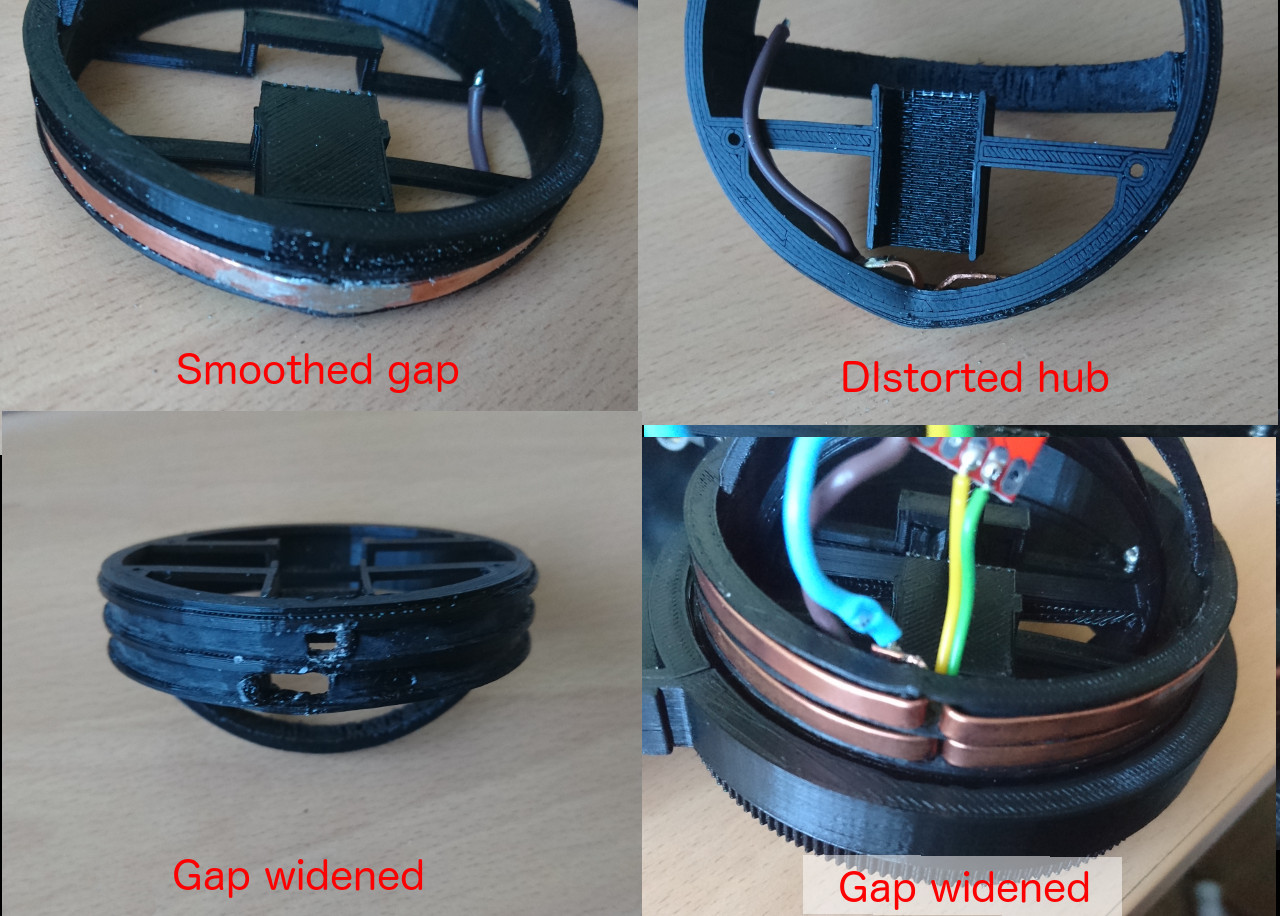
Copper Ring Gap

Copper Ring Gap 1Copper Ring Gap 2

As mentioned earlier the only part of the process that was left to finish our slip rings is soldering two ends and create smooth transition between to ends, tabs pushed through the gap to inside the wheel hub. But, we discovered, hard way, that temperature needed to solder wire to tabs is much greater than temperature needed to melt plastic (PLA in our case, but even ABS has quite a low temperature where plastic becomes soft). Also, even though copper is used to 'disperse' heat (in heat sinks for instance) it is at the same time quite good in conduction it!

Distorted Wheel Hub

YTransferring Power To Wheels


Transferring Power To Wheels

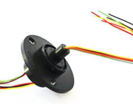
Slip Ring For wheels to turn (steer) 360º we cannot have wires going directly to motors and get twisted. Original idea was to go with a ready-made slip ring like this:
It has 6 independent wires were supposed to handle enough current with acceptable resistance but there was one snag: it would need to go directly at the 'Z' axis over the wheel. That wouldn't be an issue if we didn't plan to have absolute positioning which would use AS5600 (digital potentiometer) which requires tiny, button style magnet to occupy exactly the same place - the top of the wheel (wheel arch really) in the dead centre.

Alternatives

If we are not able to use ready made slip ring there are other options. One is to make our own or to try to pass power in contactlessly. Third option would be to not allow wheel go more than, let's say, 720º; count turns and 'rewind' back when needed. That would, after all, defeat idea of effortlessly steering with 360º freedom.

Rotary Transformer

A device that can allow that is called "Rotary Transformer" and is coming in one of two flavours: axial where windings sit inside each other and "pot core" where windings sit one on 'top' of another:

Pod And Axial Rotary Transformer

For such transformer to work we would need to make two coils, make DC to AC circuit and then add rectifier in the wheel hub as well. Not a small feat - especially for such a short time we have to sort out everything else for our rover...

More about that in this really nice master thesis of Mattia Tosi.

Slip Ring

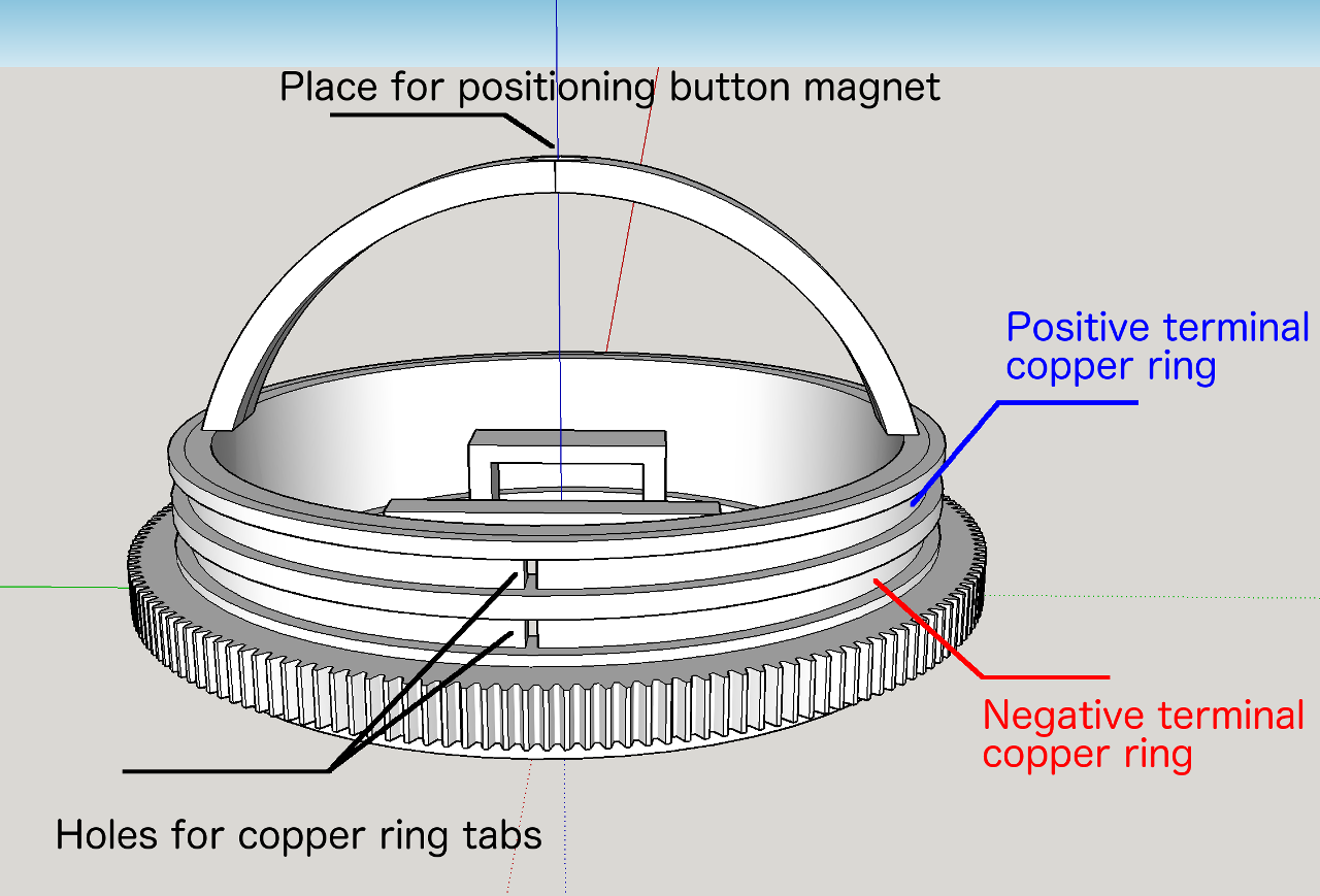
So, the alternative is to make our own slip ring then. Since top of the wheel is taken for button magnet, we can position slip rings around the wheel - in same axis as main, big bearing is sitting. So, the plan is to make two copper strips that go around the wheel hub and use existing brush motor brushes to deliver plus and minus terminals of battery to inside of the wheel hub. We started with 3mm wide and 0.3mm thick slug repellent self adhesive tape. But, on the second thought 0.3mm thick tape is going to be quite thin and possibly rip on the excessive use. Next, slightly more robust solution is 4mm wide and 1mm thick copper plates ordered from the ebay. 1mm thickness is going to ensure life time endurance and Bosh brushes (the cheapest, smallest sold on the ebay again) are 4mm thick anyway so they seemed as a good match.

Design is like follow:

Wheel Hub Design

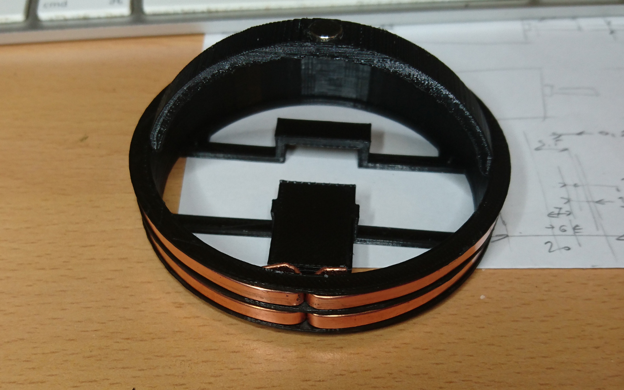
When printed it looks like this:

Printed Wheel Hub

Now, the internal tabs are going to be connected to motor controller (H bridge of some kind) for power and to voltage regulator for ATmega controller, nRF24L01 transceiver for communication to RPi and AS5600 as a wheel's "rotary encoder" sensor...