Clustered PyROS


Clustered PyROS

It seems that one Pi is not enough. Our rover is, now, equipped with Adafriut's 9-dof breakout board with gyroscope/accelerometer and compass modules, touch screen, 8 x VL53L1X sensors, 4 AS5600 magnetic sensors, nRF24L01 for talking to wheels and another piece of hardware that goes to SPI interface.

9-dof module can be run on i²c bus, but it might saturate it and we already have VL53L1X modules that have to be run on i²c bus. One Raspberry Pi would need to read 4 magnetic sensors to steer wheels, 8 distance sensors to determine surroundings of the rover, read compass, gyro and accelerometer to try to deduct our position (which, itself is quite CPU heavy), draw on screen and have spare CPU capacity for running PyROS and challenge code. Quite a lot and some of them (9 dof data) are time sensitive.

Here is breakdown based on which buses different devices use:

  • 9-dof can use i²c or SPI (two SPI devices - one for gyro/accelerometer and one for compass)
  • 4 x AS5600 i²c with multiplexer
  • 8 x VL53L1X i²c with multiplexer - two devices on same channel
  • nRF24L01 SPI
  • touch screen SPI
  • another device on SPI

Read more…

Telemetry


Telemetry

There are a few ways of developing your code on Raspberry Pis for PiWars: - write your code on Raspberry Pi using monitor and keyboard attached to the RPi - write your code on Raspberry Pi using ssh - write your code on Raspberry Pi using X11 tunnelled back to your computer/laptop's X11 Terminal (client program) - write Python on your laptop/computer, copy it to Raspberry Pi (scp/samba/...), ssh back to RPi to run it - use sophisticated IDEs like Pro version of PyCharm that know how to execute Python code remotely piping shell output back to IDE's console - use PyROS

I've enumerated options from simplest to most complex and from least convenient (it is quite hard chasing your rover with monitor and keyboard in your hands while attached to it) to most convenient. Having IDE doing heavy lifting for you (Pro version of PyCharm) is very useful but it costs money (£70 a year for individuals). Using PyROS is almost as easy as IDE - at least can be made easy.

$ pyros myrover upload -s -r -f wheels wheels-controller.py

This would be an example how to upload new version of 'service' wheels (python file wheels-controller.py) and keep the 'connection' on (-f option) - pumping 'logs' (stdout) back. If at any point you stop it you can continue monitoring stdout from a service by:

$ pyros myrover log wheels

But, all those predicate you use print statements in Python to log what is going on with you code. In case (as it is ours) we have a few loops running at significant speeds (over 200Hz) gathering data (from AS5600 for wheel orientation, accelerometer, gyroscope and compass from IMU and such). Just imagine the amount of text printed out all the time to stdout. Also, as PyROS utilises MQTT for communication between processes (and shell commands as above) it would make output really big and 'clog' network throughput. Additional problem is that not all output is coming from the same PyROS 'service' (an unix process maintained by PyROS) - so you would need to simultaneously monitor several process logs.

Requirements

One option would be to write to log files. But, then, how far you can go with writing to SD card? It has limited throughput as well. Then you would create several files, which would need to be downloaded after the run and analysed in parallel. Not an easy job. All of this lead us to decide to create simple data gathering system - a simple telemetry library!

Ideas were like following: - ability to define the structure of data - ability to 'pump' larger amounts of structured data to the logging system - ability to fetch data on demand from client/analysing software - nice to have: ability to produce aggregate of gathered data for real time telemetry

So, here it is - small side project of Games Creators Club: GCC-Telemetry

Read more…
Making Brushes


Making Brushes

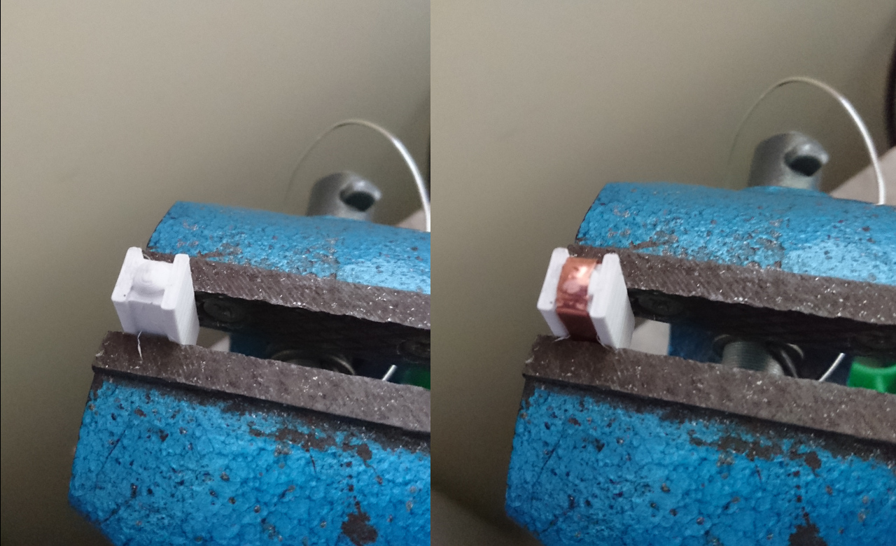
The last bit that remains for ensuring constant delivery of power to the wheels are brushes. A friend of GCC, practically a team member Saša (he provided us with 3 way sonic control breakout board we, end the end, didn't get chance to use as such - but as breakout board for driving servos for the nerf gun) suggested that brushes should follow what we normally see in mechanical relays and real motor brushes: instead of insisting on contact of a flat plate we should provide more of a spherical shape of the brush. That would allow it to overcome tolerance issues we have with 4mm slip ring, 3D printing and such and provide nice contact.

So geared with that idea we came with a solution: a tool that can help us shape 0.3mm x 4mm copper strip to appropriate shape needed - needed not only for spherical 'bump' but rest of it to fit nicely into our 'spring and brush' holders. here's a 'Brush Tool':

Making a Brush

Read more…

Putting All Together


Putting All Together

Now it is time to continue with our build. The wheel hubs are done, the design for the main body is ready - it is time to put all together!

Top Platform

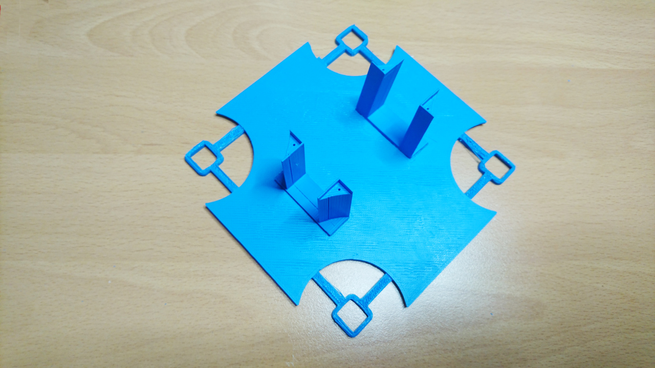
To start with here's the first version of 'top platform' design. At the level of main body we have bulky bearings encapsulating wheels, motors that steer wheels, brushes and space for battery. Also we need place for Raspberry Pi, steering motor controllers, DC-to-DC converter, sensors, i²c multiplexer and so many other smaller things. They all will be stored on that platform.

Read more…

3D Printing, Materials and Support


3D Printing, Materials and Support

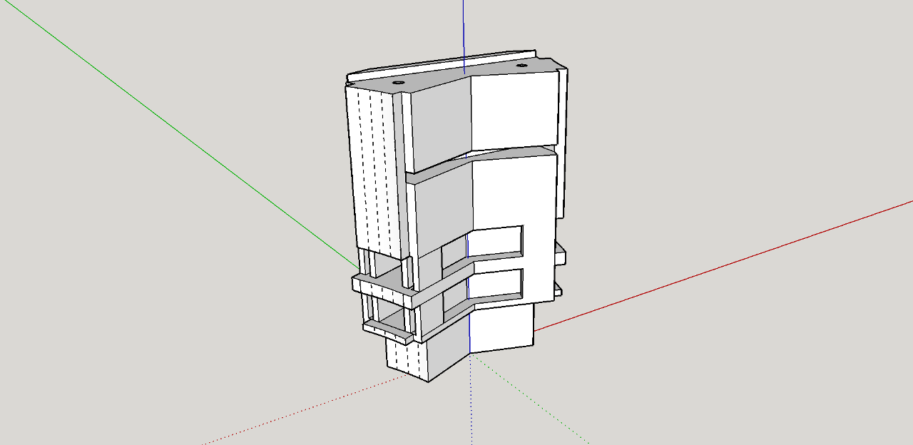
PiWars gave us opportunity to play with many different new technologies and learn new stuff. 3D printing was one of them. As our design get more complex they required more thinking and knowledge on how to produce good prints. In the previous blog Transferring Power To Wheels, Part II we talked about how orientation can help with avoiding support. But sometimes it is not as simple. A similar part again (for holding springs and brushes):

Spring Holder Design

Read more…

Losing IMU Data


Losing IMU Data

Investigation and Solution

Introduction

This article discusses some of the problems I encountered whilst using a Raspberry Pi to read data from a complex sensor at approx 200Hz.

If you're short of time, just skip to the conclusions at the end of the article.

System Overview

The system contains an IMU (an LSM9DS1), a sensor which provides acceleration, angular rate and magnetic field measurements. The IMU has a "Data Ready" output pin. It sets the pin to 1 when new data is available and clears it when the data is read. There's also an API call which provides the same information. This "Data Ready" output is connected to a GPIO input on the Raspberry Pi.

The positioning system spawns a process to gather data samples. I call this a "Data Pump".

The IMU produces samples at 230.8 Hz. i.e. once every 4.3 milliseconds.

Read more…

i²c Multiplexer


i²c Multiplexer

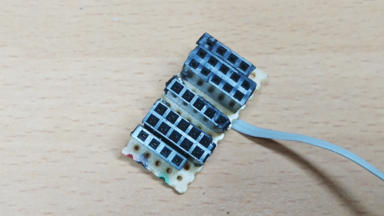
For steering wheels we need 4 x AS5600 and, unfortunately, AS5600 only has one i²c address and it cannot be moved. So the only way to overcome this problem is to introduce an i²c multiplexer - a chip to allow splitting of i²c bus to many sub-buses. For this we chose PCA9545A, a 4 way multiplexer. But they don't make it in DIP packages as well and 24 pin adapter was in order, too.

But, 4 way multiplexer has quite a few wires, especially if we want to use each sub-bus several times. For instance, on each sub-bust we can put two VL53L1X with only one extra GPIO (to discriminate between two VL53L1X sensors in setup). That would mean that from this tiny chip we would need to draw 5 (GND, VCC, SDA, SCL, GPIO) x 3 (2 x VL53L1X and AS5600) x 4 (4 sub-buses) + another 5 (GND, VCC, SDA, SCL, GPIO - connection to main bus) lines. 64 in total! OK, we can omit 4 x GPIO to AS5600 but that's pretty much it. Here's what we did to alleviate situation:

Step 1

Read more…

Hub Controller


Hub Controller

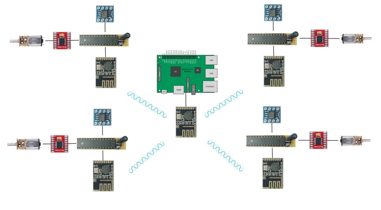
Now we have sorted out getting power inside of wheel hub - next is to control the wheel. The wheel needs to know should it spin, which direction, which speed or if it should stop. Also, since we opted for AS5600 (12-bit Programmable Contactless Potentiometer) for a 'rotary encoder' we would like to have the position of each wheel reported back to the RPi.

For the brain behind the controller we have chosen ATmega328p - a well known µController used in Arduinos. Its responsibility here is to the control H bridge using PWM (using 8-bin Timer 0), read from AS5600 using i²c and listens requests from Raspberry Pi - controlling nRF24L01 using SPI interface.

Diagram

Read more…