YClustered PyROS
Clustered PyROS
It seems that one Pi is not enough. Our rover is, now, equipped with Adafriut's 9-dof breakout board with gyroscope/accelerometer and compass modules, touch screen, 8 x VL53L1X sensors, 4 AS5600 magnetic sensors, nRF24L01 for talking to wheels and another piece of hardware that goes to SPI interface.
9-dof module can be run on i²c bus, but it might saturate it and we already have VL53L1X modules that have to be run on i²c bus. One Raspberry Pi would need to read 4 magnetic sensors to steer wheels, 8 distance sensors to determine surroundings of the rover, read compass, gyro and accelerometer to try to deduct our position (which, itself is quite CPU heavy), draw on screen and have spare CPU capacity for running PyROS and challenge code. Quite a lot and some of them (9 dof data) are time sensitive.
Here is breakdown based on which buses different devices use:
- 9-dof can use i²c or SPI (two SPI devices - one for gyro/accelerometer and one for compass)
- 4 x AS5600 i²c with multiplexer
- 8 x VL53L1X i²c with multiplexer - two devices on same channel
- nRF24L01 SPI
- touch screen SPI
- another device on SPI
RPi SPI
So, if we go with a 9-dof on SPI bus, then we would need 5 SPI devices attached to the same bus. Fortunately RPi allows more than default 2 devices being attached to the same bus.
Richard has cracked that as well. To have more than two devices on SPI we need device-tree-compiler:
sudo apt-get install device-tree-compiler
Next is to fetch four-chip-selects-overlay.dts file and execute
dtc -@ -I dts -O dtb -o four-chip-selects.dtbo four-chip-selects-overlay.dts
sudo cp four-chip-selects.dtbo /boot/overlays
That will add two more devices on GPIOs 7 and 8, aside of default on GPIOs 24 and 25. See the four-chip-selects-overlay.dts file.
To enable the overlay you need to edit your /boot/config.txt file to include
dtoverlay=four-chip-selects
This will assign pins GPIOs 24 and 25 to CS2 and CS3 respectively.
You can specify different pins if you want
dtoverlay=four-chip-selects,cs2_pin=24,cs3_pin=25
But, 9-dof data is sensitive and nRF24L01 is quite chatty and can jump-in in the worst possible time. So, it makes sense to offload talking to wheels to separate Raspberry Pi. If talking to wheels goes to PiZero then steering wheels can go there (4 x As5600 and 2 GPIOs per wheel - 8 in total!), too; actually motion control itself. But, since we need (can't avoid) i²c multiplexer for AS5600 sensors, then it makes sense to move VL53L1X to the same device, too.
On the main RPi we'll be left with touch screen (very low frequency, not time issues) and 3x SPI for positioning (9-dof and another device) - four it total.
PyROS
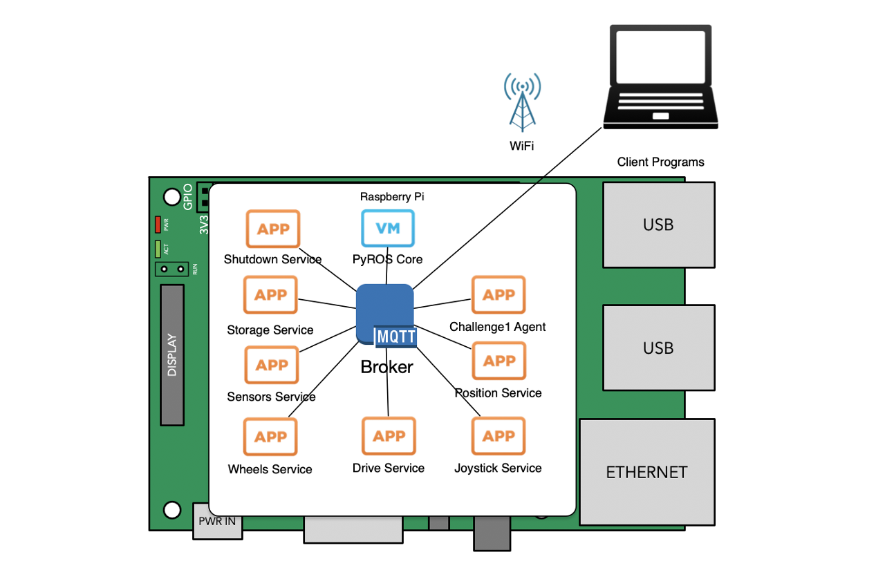
Now, since code is going to be split across two devices the question was how to mange it. On one device all is managed by PyROS:

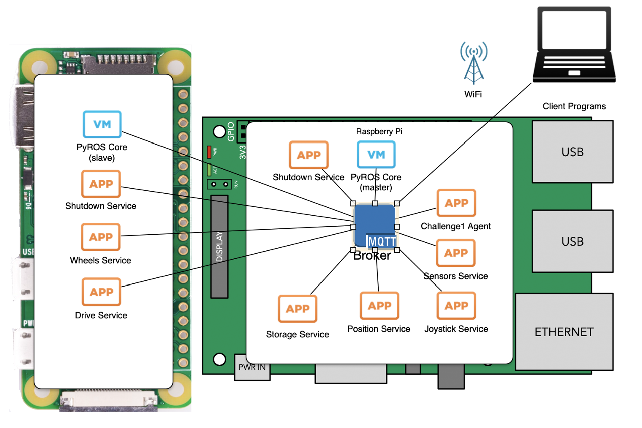
Wouldn't it be nice if the same, central control can be applied to second Raspberry Pi? Since Raspberry Pies are to be networked (look below) then there's no reason for PiZero to use Raspberry Pi 3's (B+) MQTT broker, too!
Total changes to the PyROS were minimal: each process id (name of service/program/agent) now can be prefixed with Pi we want it to go to and only PyROS main process that identifies itself with it (let's call it clusterId - or id within cluster) would react on message. Only 'global' message both react is ps command, but that's fine as result is collected from MQTT particular topic within timeout and if both respond at the same time - two messages are going to be delivered to the client and both processed and displayed. Also, if process id is not prefixed then only 'master' Raspberry Pi will react - in the same way as now.
Another simple change was to provide device identifier through exporter shell variable (CLUSTER_ID) and propagate it to all sub-processes PyROS is maintaining.

Now, PiZero detailing with wheels is called (imaginatively, right?) 'wheels' and uploading 'wheels' service to it looks like this:
pyros rover6 upload -s -r wheels:wheels wheels_service.py
Pi Networking
As mentioned above PiZero is going to be networked with Raspberry Pi 3. The simplest way seemed to be using USB for both power and networking. Fortunately PiZeros are well know that can provide 'ethernet gadget' (or 'ethernet USB device') and that is done by adding:
dtoverlay=dwc2
to /boot/config.txt and adding
modules-load=dwc2,g_ether
after rootwait to /boot/cmdline.txt file. After attaching PiZero to Raspberry Pi 3 new network interface called usb0 appeared and automatically local-link address was assigned to both Raspberry Pi 3 and PiZero devices. But, in our case we would really like to have static IP for Raspberry Pi 3 so its MQTT broker can be easily reached. Beside that, we would really like Raspberry Pi 3 to act as gateway and NAT our access to the rest of the world. That's slightly more involved:
First we need to allow IP Forwarding by uncommenting line net.ipv4.ip_forward=1 in /etc/sysctl.conf
Next is to setup IP tables to route packets. Manually it can be done by:
sudo iptables -A FORWARD -i usb0 -o wlan0 -j ACCEPT
sudo iptables -A FORWARD -i wlan0 -o usb0 -j ACCEPT
sudo iptables -t nat -A POSTROUTING -o wlan0 -j MASQUERADE
But it is not permanent solution. The same setup can be 'dumped' to a file and that file would look like this:
# Generated by iptables-save v1.4.21 on Mon Jan 21 12:58:21 2019
*nat
:PREROUTING ACCEPT [10:739]
:INPUT ACCEPT [0:0]
:OUTPUT ACCEPT [5:572]
:POSTROUTING ACCEPT [2:344]
-A POSTROUTING -o wlan0 -j MASQUERADE
-A POSTROUTING -o wlan0 -j MASQUERADE
COMMIT
# Completed on Mon Jan 21 12:58:21 2019
# Generated by iptables-save v1.4.21 on Mon Jan 21 12:58:21 2019
*filter
:INPUT ACCEPT [8271:443643]
:FORWARD ACCEPT [0:0]
:OUTPUT ACCEPT [8108:437571]
-A FORWARD -i usb0 -o wlan0 -j ACCEPT
-A FORWARD -i wlan0 -o usb0 -j ACCEPT
-A FORWARD -i usb0 -o wlan0 -j ACCEPT
-A FORWARD -i wlan0 -o usb0 -j ACCEPT
COMMIT
# Completed on Mon Jan 21 12:58:21 2019
Save such file somewhere in /etc (for instance /etc/usb0_rules). Next is to ensure those rules are added at the time
usb0 is attached. The New file /lib/dhcpcd/dhcpcd-hooks/80-usb0:
# usb0 up after assign ip address
if [ "$interface" = "usb0" ] && [ "$reason" = "STATIC" ]; then
        iptables-restore < /etc/iproute2/usb0_rules
fi
ensures that rules are run after usb0 interface is added. But we need to tell dhcpcd that we would like static IPs on usb0 interface. It can be done by adding following to /etc/dhcpcd.conf:
interface usb0
static ip_address=169.254.1.1/16
Now, we'll apply the same process for usb1 and usb2 and allow two more PiZero devices to be added, too. Why? Well, it is secret for now ;)