Putting All Together
Putting All Together
Now it is time to continue with our build. The wheel hubs are done, the design for the main body is ready - it is time to put all together!
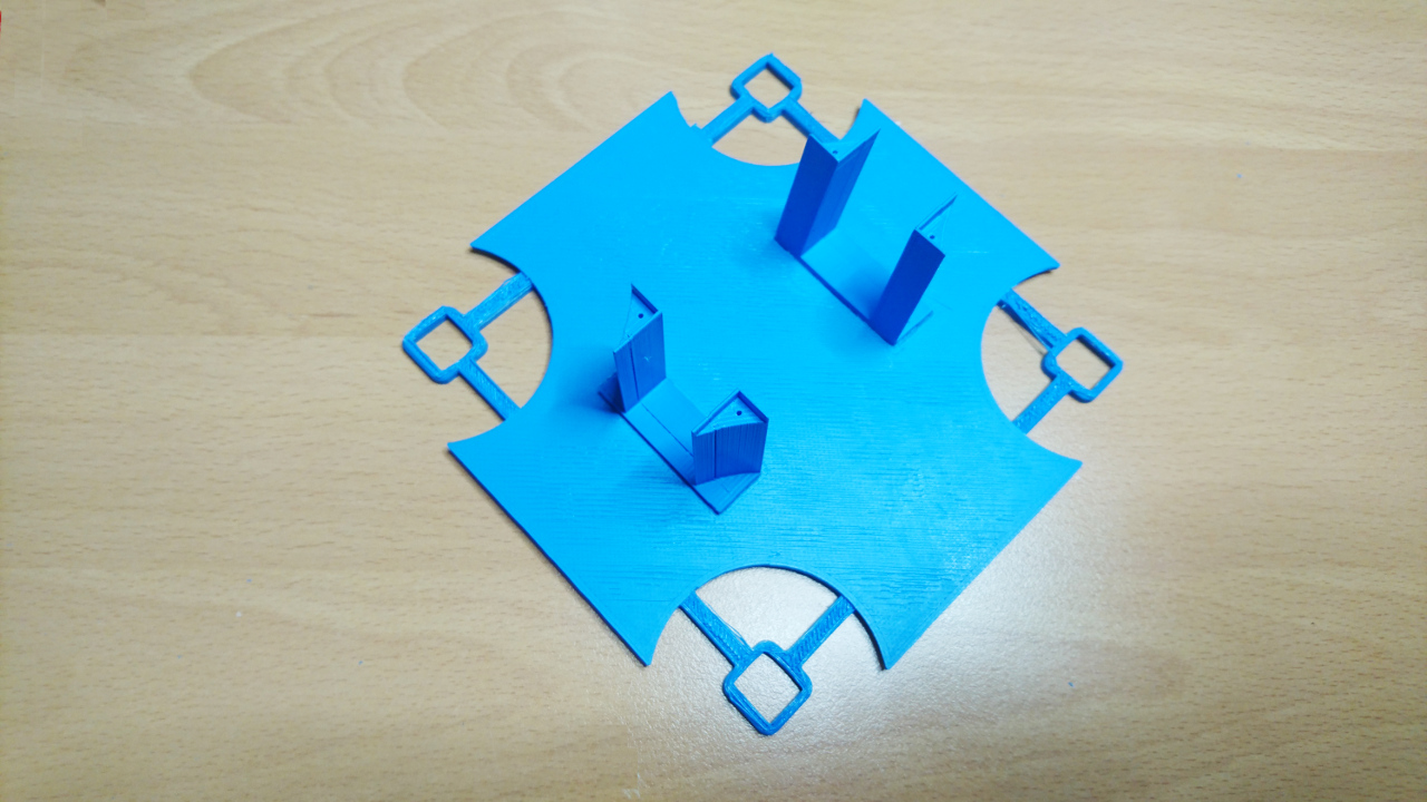
To start with here's the first version of 'top platform' design. At the level of main body we have bulky bearings encapsulating wheels, motors that steer wheels, brushes and space for battery. Also we need place for Raspberry Pi, steering motor controllers, DC-to-DC converter, sensors, i²c multiplexer and so many other smaller things. They all will be stored on that platform.
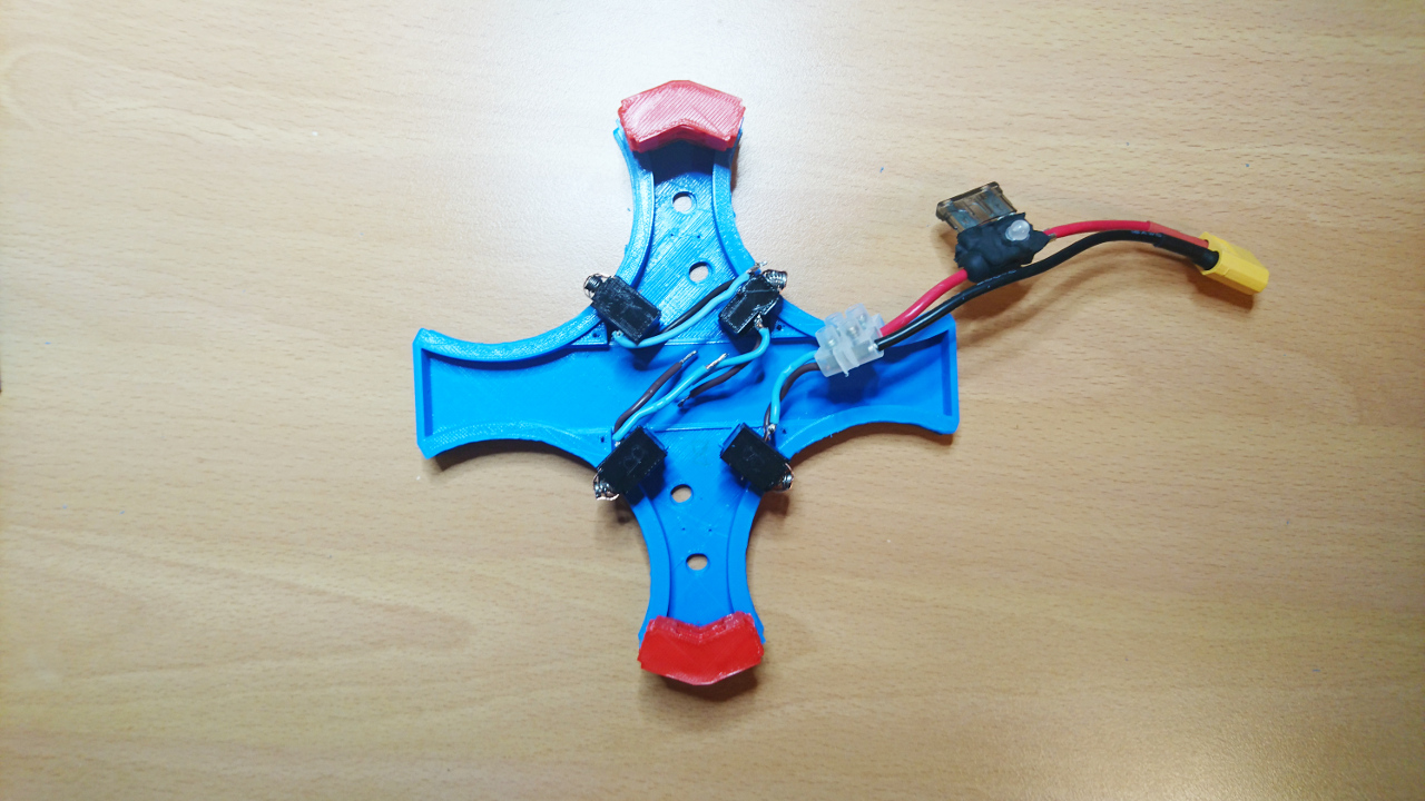
Now here is main body with main brushes and battery connector.
Next is to add bearings, wheel hubs, clamps to hold bearings and platform holders:
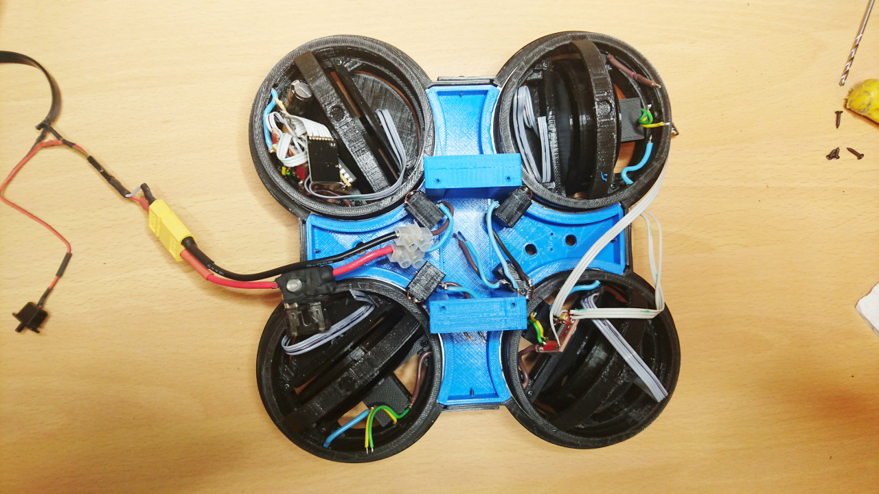
Now we can add steering motors and gears:
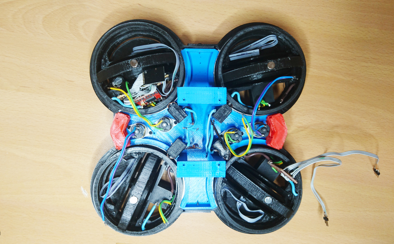
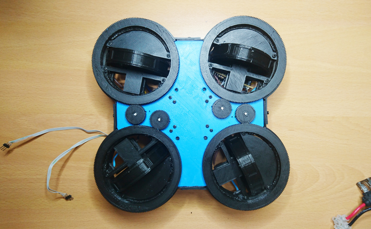
This is how complete body layer looks with connectors added for brushes:
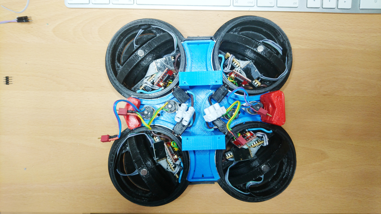
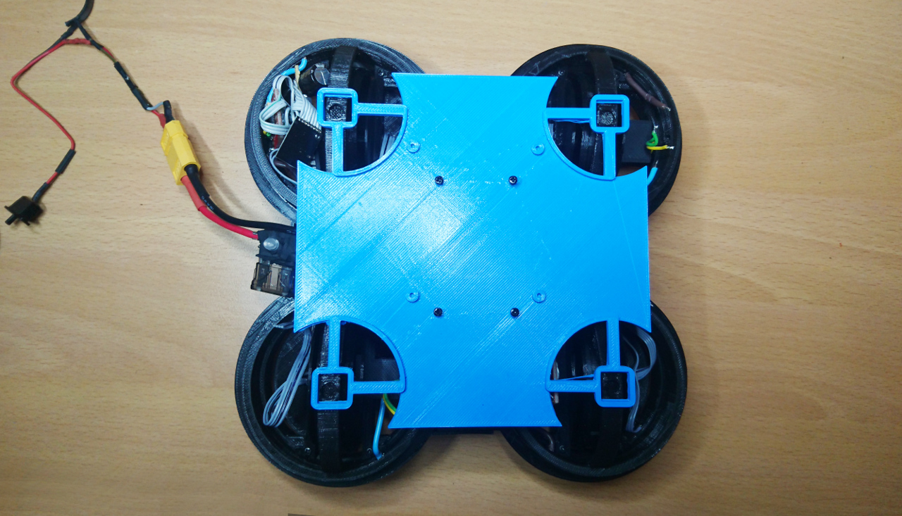
And when everything is covered with 'top platform':
Steering Motors and Controllers
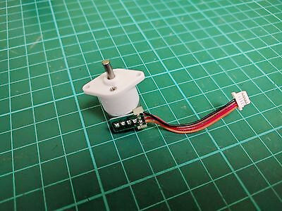 Tiny geared motors used in the body for steering are as well "Plan B" motors. The original idea was to go with geared micro stepper motors but that caused a few issues: they weren't fast enough, they were strong enough and there was an issue if driven too fast - there wasn't a suitable feedback that motor didn't really move whole step as required. Too many little problems that were supposed to be fixed. The original idea was that wheels would have some 'starting point' a contact to denote particular position or tab to cut IR LED/IR Photo Diode setup similar to old fashion mice (there was a wheel with slots moving in the middle of such setup). Wheel would at the start up move to such position and after that counting steps we would be able to say exact position of the wheel. But, if stepper can miss a step - whole idea would fall through as wheel might end up being in completely wrong position to what system believes it is. So, AS5600 + simple DC motor is solution forward.
Now, we've got a few kind of micro geared DC motors for previous PiWars. Some marked as '150RPM', some '200RPM' and some '300RPM'. Others are marked as geared as 20:1 and 50:1 and both were geared 'faster' than 300RPM. All at 6V. The plan was to pick the fastest and make it turn the wheel. So, we started with 200RPM. Motors turned the wheels well @ 5V (we started with simple phone charger voltage) but not fast enough. Then we switched it to 50:1 geared motor and it couldn't turn it at all. It wasn't strong enough!
Over time we moved to battery's 8V (actually 9.4V from another AC/DC adapter first) and 200RPM motors performed adequately but was that the best we could do?
Then due to some unidentified issue one geared motor got stuck and brew motor controller (H bridge)! That prompted software change - if wheel doesn't reach required position for couple of seconds, it would be switched off for another couple of seconds for H bridge to 'cool off'. At the same time tiny motor was replaced but replacement didn't behave as expected: occasionally it struggled with load! After closer inspection we saw it was 300RPM motor - and that sorted it: '200RPM' we have originally put are the fastest we can go with.
It seems that there are plenty of improvement pending in that area as well - provided we have time. The 'only' thing we need to do is to source slightly better, stronger and slightly faster motors to replace these tiny geared (to '200RPM' @ 6V) motors...
Comments
Comments powered by Disqus