YPrototyping
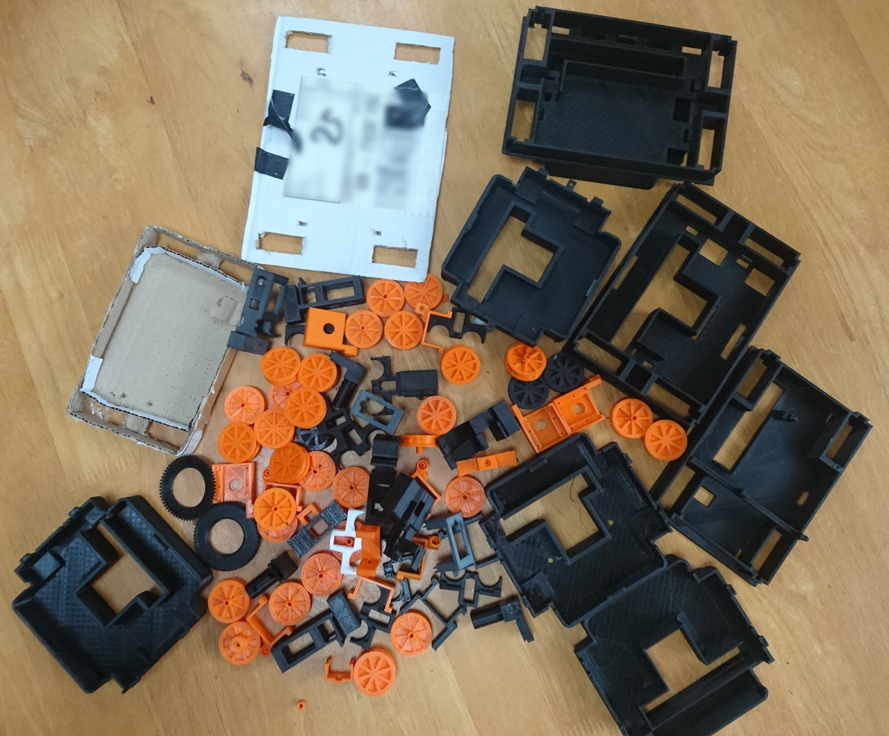
It is time for prototyping again! For our first PiWars we adopted iterative approach: design, mock, test, improve and repeat. That lead to lots of iterations and lots of discarded parts.
But was that necessarily a bad thing? So far it seems that at least half of the 'previous versions' have found a kind of home - for people who wanted to try putting together a rover of ours and are not worried having the latest, the most refined version of it. Also, it helped us to find out what the 'dead ends' and the 'wrong decisions' were like and we learned from them. Beside that, it made our club members not be scared of trying out stuff even if it originally seems not to be the best idea that we can come up with at that moment.
Now we are at quite a few new designs. One of the first we did was PiNoon capture nut (ahm, electric connector) and with distance sensor (VL53L0X). One of the previous blogs was about capturing stuff in 3D printer objects.

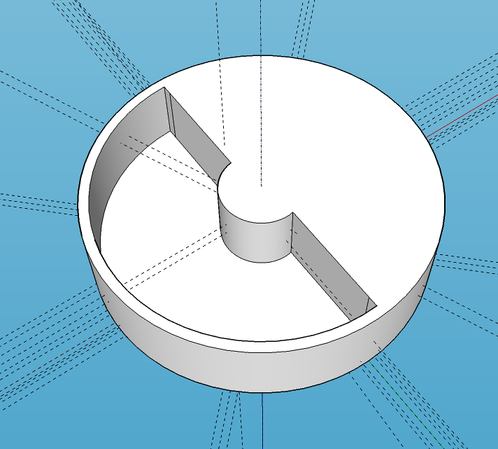
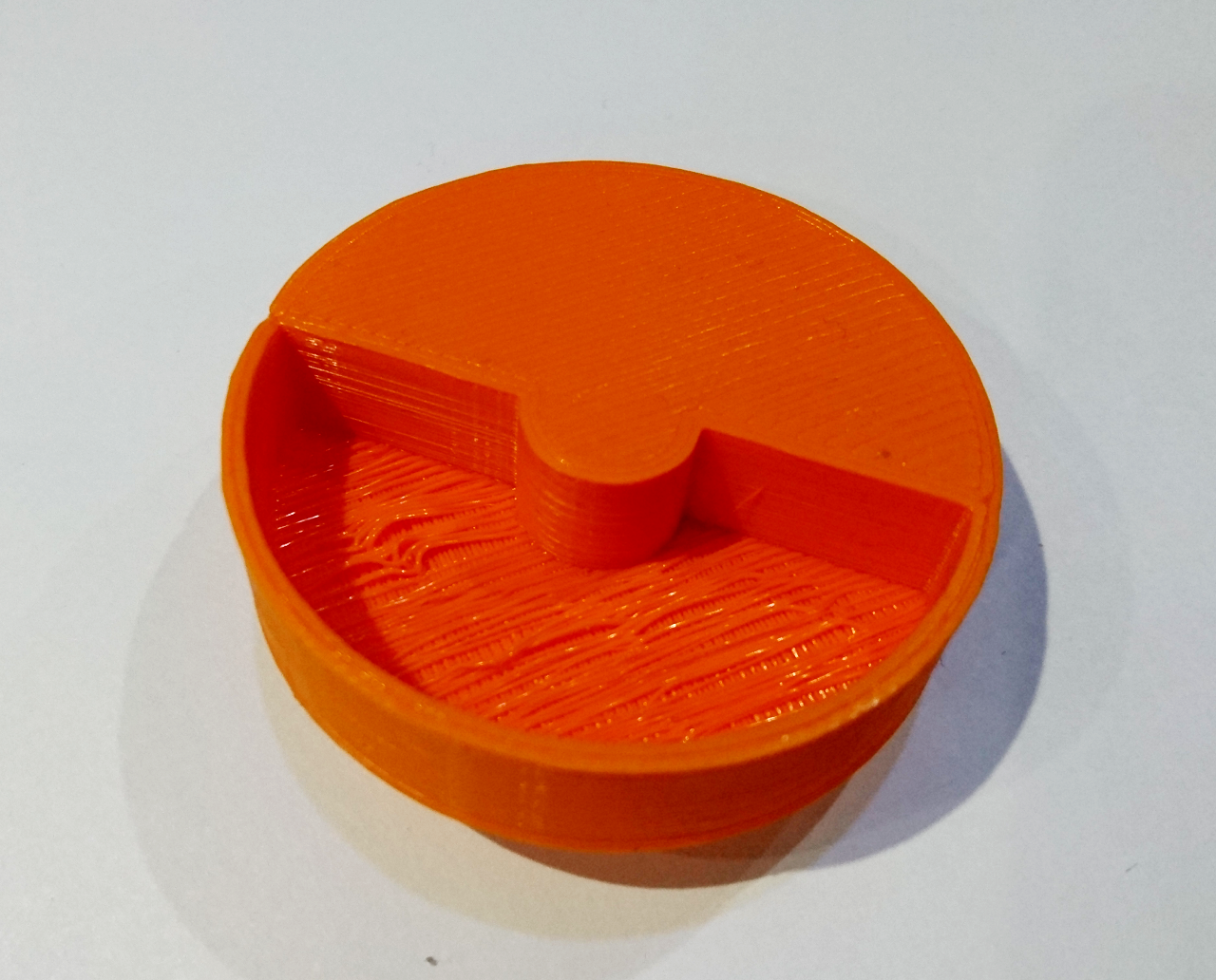
 Next was a wheel to help us calibrate the (non load) speed of the motors. It is half filled in and half 10mm indented - an attempt to use same distance sensor for calibrating speed of the wheel. The idea is to put the sensor at some close range (10-20mm) and spin the wheel, counting how many times a second it measured the shorter distance to longer distance. Its target speed can be 120RPM, which is 2 times a second - and the default VL53L0X 'time allowance' is 33ms, we should be able to do 30 samples of which 15 should be shorter distance and 15 longer. The software for it is still pending.
Two Distance Sensors Holder
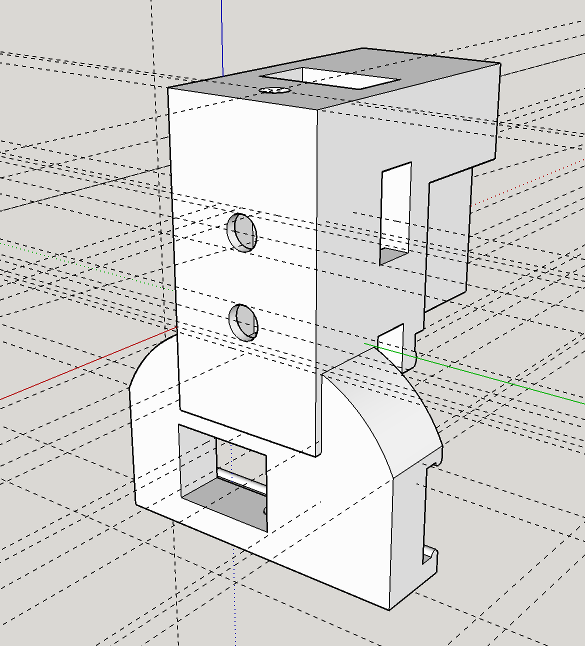
The last design is our work towards The Minimal Maze and Somewhere Over The Rainbow. The two VL53L0X sensors at 90º attached to our standard front, downward facing servo will be quite a complex 3D design.[gallery ids="1176,1175,1173" type="rectangular"]
Originally it was designed as two parts but as 3D printers can print things with support material - this was the perfect candidate for it. So, here is the redesigned model:
[gallery ids="1177,1172,1171" type="rectangular"]
One of the following blogs will cover the connecting of two VL53L0X sensors using a FET transistor as a NOT gate...
Aside of those there are still outstanding for capturing the golf ball for Slightly Deranged Golf and The Duck Shoot that are still to be built. More about it later.