Yi²c Multiplexer
i²c Multiplexer
For steering wheels we need 4 x AS5600 and, unfortunately, AS5600 only has one i²c address and it cannot be moved. So the only way to overcome this problem is to introduce an i²c multiplexer - a chip to allow splitting of i²c bus to many sub-buses. For this we chose PCA9545A, a 4 way multiplexer. But they don't make it in DIP packages as well and 24 pin adapter was in order, too.
But, 4 way multiplexer has quite a few wires, especially if we want to use each sub-bus several times. For instance, on each sub-bust we can put two VL53L1X with only one extra GPIO (to discriminate between two VL53L1X sensors in setup). That would mean that from this tiny chip we would need to draw 5 (GND, VCC, SDA, SCL, GPIO) x 3 (2 x VL53L1X and AS5600) x 4 (4 sub-buses) + another 5 (GND, VCC, SDA, SCL, GPIO - connection to main bus) lines. 64 in total! OK, we can omit 4 x GPIO to AS5600 but that's pretty much it. Here's what we did to alleviate situation:
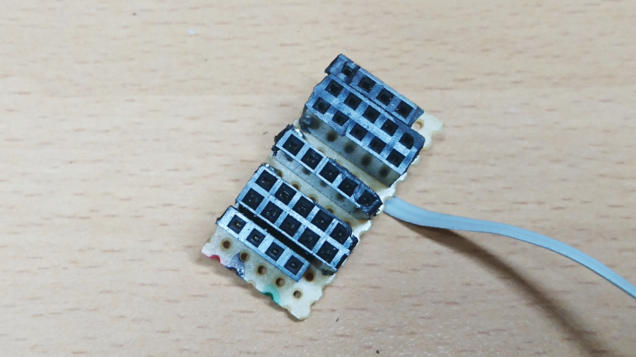
The first part of board is a 2 set of 3 i²c 'sockets' - each set for one sub-bus having two with 5 pins (GND, VCC, SDA, SCL and GPIO for VL53L1X) and one only four (GND, VCC, SDA and SCL - for AS5600). Also, middle one is directly on 'master' bus. Those two that have 5 pins, one of them is connected to GPIO and one isn't.
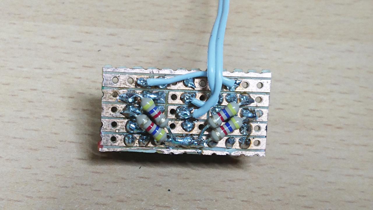
Next is to add pull up resistors to SDA and SCL lines for each sub-bus. Then, replicate that little board one more time. After that we need to connect both sides together:
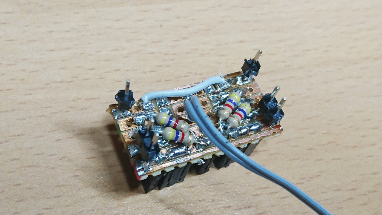
To do so we used simple male pins to keep distance and electrically connect two opposite sides. GND, VCC and GPIO have to be connected together and only those pins are used.
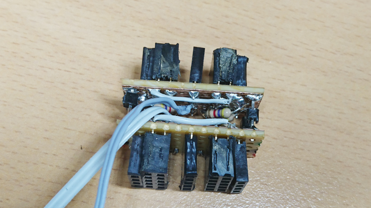
Finally - when all is put together we wired GND, VCC and GPIO lines towards the master bus (Raspberry Pi) and connect 4 sub-buses' SDA and SLC to the multiplexer, along with GND and VCC and add SDA and SLC connections to the master bus (Raspberry Pi's i²c)
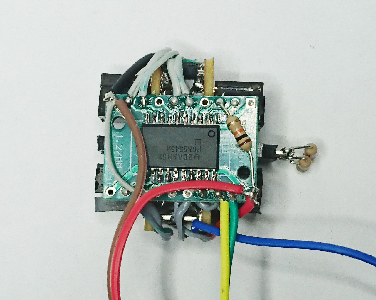
Now we have 4 sub-buses, each with 3 separate connections and pull up resistors. Also, we have two separate connectors on master bus. One will serve for 'further' expansions and another to connect pull up resistors for the master bus (right hand side on the picture).