Hub Controller
Hub Controller
Now we have sorted out getting power inside of wheel hub - next is to control the wheel. The wheel needs to know should it spin, which direction, which speed or if it should stop. Also, since we opted for AS5600 (12-bit Programmable Contactless Potentiometer) for a 'rotary encoder' we would like to have the position of each wheel reported back to the RPi.
For the brain behind the controller we have chosen ATmega328p - a well known µController used in Arduinos. Its responsibility here is to the control H bridge using PWM (using 8-bin Timer 0), read from AS5600 using i²c and listens requests from Raspberry Pi - controlling nRF24L01 using SPI interface.
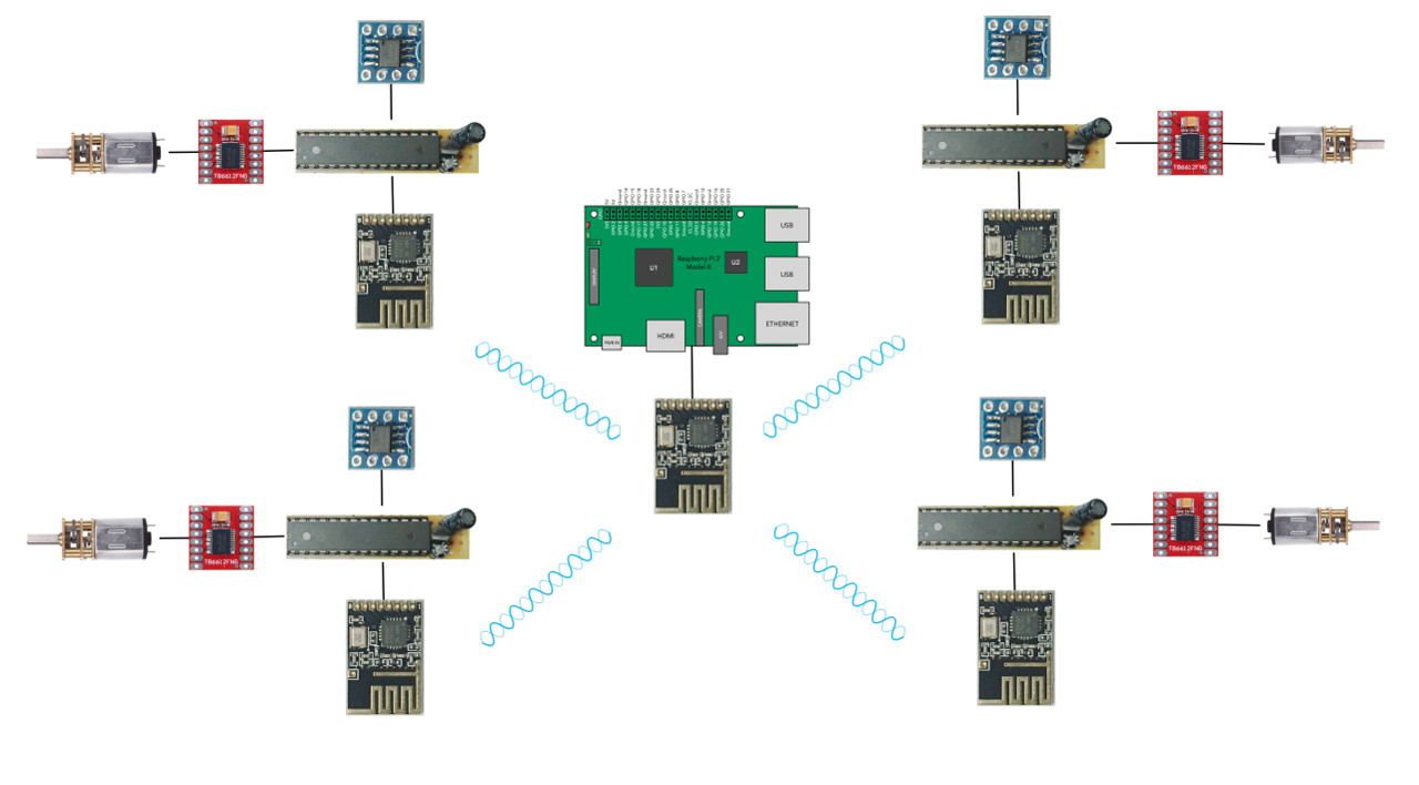
ATmega328
ATmega328p is a perfect little controller - it draws very little current, it is easy to program for and has enough support for peripherals we need: i²c, SPI, PWM and such. Original code I did in assembler (old - more than 20 years old habit), but after some thinking and introducing a PID algorithm into the picture we changed our mind and decided to go with something where float point arithmetics would be simply given. I've started with Artudino IDE stuff but there are so many little gotchas and pre-defined usage of a µController's resources that it didn't make much sense continuing with it. After a bit of help from Brian @ UsedBytes (thank you a lot for all the help) I've decided to go with slightly lower level AVR Libc. Interesting bit was that for 80% of the time trying to re-implement assembler code to C I was comparing result from compiler with my hand-crafted one and they were quite close. Only near the end when the functions started getting bigger and more convoluted, the compilers started introducing the stuff that compilers are for: storing intermediate results on stack, passing parameters through the stack and such and resulted assembler code stopped being as readable as it was at the beginning. Nevertheless - amount of 'excess' code needed for higher level coding is (finger in the air estimation after reading it) a round 20% to what it might have been if coded and optimised by humans - quite comfortable and acceptable. Especially for the comfort of using real variables, math operations, arrays, high level control structures (if/while/for) and such.
Power To Controller And Peripherals
The wheel hubs are powered directly from a LiPo battery at around 8V. The controller and peripherals (AS5600 and nRF24L01) require 3V3 so next to µController we need a voltage regulator. Fortunately all of them are really low current consumers so a tiny LE33C2 is more than sufficient. But, since we have sliding contacts - slip rings, power can actually fluctuate. To sort it out (in the short term) we used quite bulky capacitors - 470µF. Also, software is made to detect the µController 'browning out' and pass that information in the next status update (when its powered up again).
AS5600
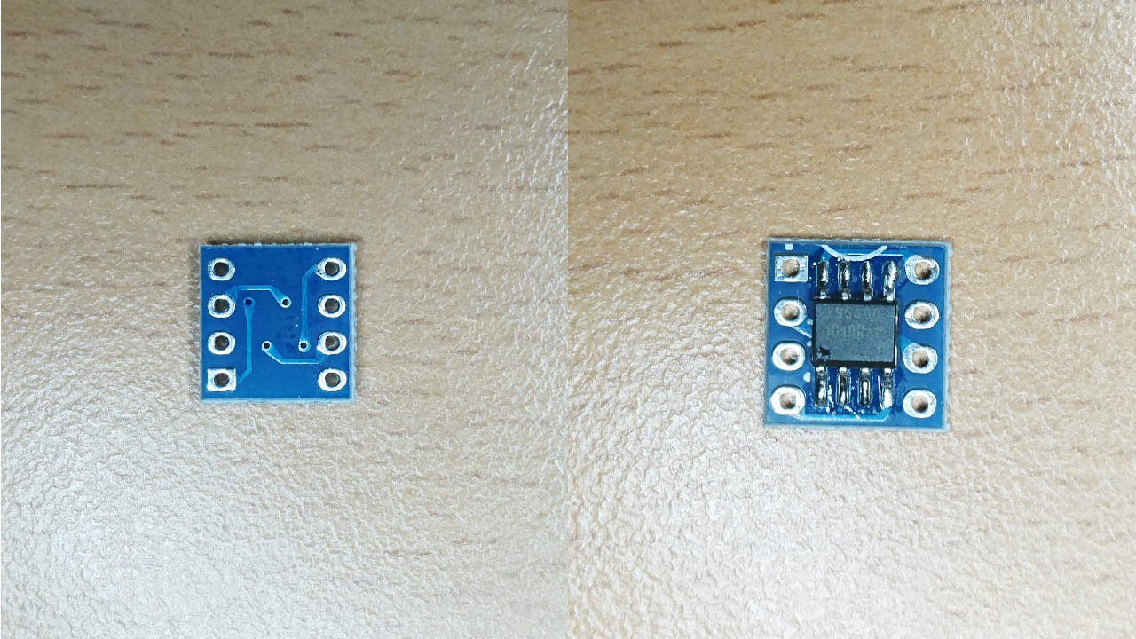 It seems like a really nice and easy chip to communicate with and works 'out of the box'. First it needs a button sized magnet placed really close to it (see out wheel design), 4 wires connected to the µController (GND, VCC, SDA and SLC) and, what we learned hard way, DIR connected to GND or VCC to determine the 'direction' that the AS5600 will report. Doesn't matter what we select for the direction as we'll easily handle it in the calibration process on the Raspberry Pi.
The next problem is that it is only produced in SOIC8 packaging - perfect for big numbers machined in PCBs - not so good for enthusiasts' projects. In order to make it more manageable we've first solder them to SIOC8 to DIP8 adapter
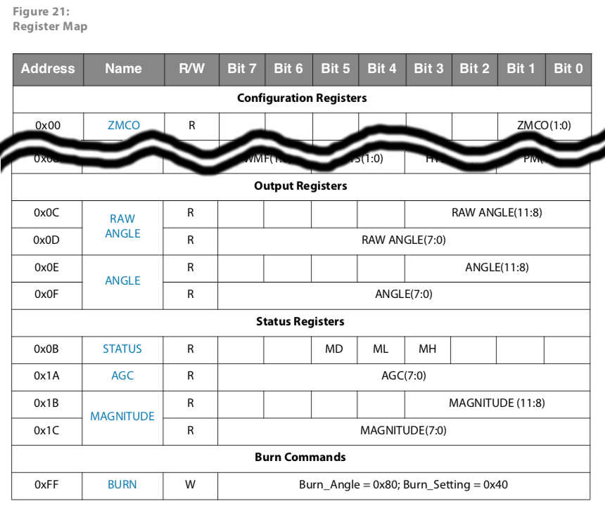
And, for software, all we need to do is to read the ANGLE and STATUS registers. Now, the STATUS register is at 0x0B address and angle at 0x0E address with 0x0C and 0x0D (RAW ANGLE) in between. It seems faster to read all from 0x0B to 0x0F (STATUS, RAW ANGLE and ANGLE) - 5 bytes or 7 in total reading/writing of i²c in comparison to two separate reads.
ANGLE is going to give us 12-bit (0-4095) absolute angle of the position of the wheel and µController is going to relay it back in it's response. Also, it can be internally used for PID controller for maintaining required speed.
nRF24L01
nRF24L01 is really nifty little transmitter that does quite a lot of heavy lifting in 2.4GHz spectrum range for us. Limitation is that it can only transfer packets up to 32 bytes long. Fortunately we don't need that much to convey all we need from Raspberry Pi to motor (mode to operate in, speed and maybe a few other bits and pieces) or from motor to Raspberry Pi (status, position of the wheel and such).
Bootloader
Also, there's extra benefit to it, too, secret weapon of a sort: in some of previous projects I've created small ATmega328p bootloader that works over nRF24L01 Now, it is really easy to program the ATmega328p (after it was originally flashed with that bootloader) - directly from Raspberry Pi. That bootloader checks one pin and if it is connected to ground it would go directly into the bootloader. If not it will proceed to the uploaded program.
Our wheels are powered through an unreliable power source we cannot rely that we'll be able to react and move µController to application as quickly as possible. So, bootloader pin has to be set to going to app immediately. So, the last 'ingredient' for the software for ATmega328p was special packet that would 'revert' code to bootloader - invoke bootloader from the application itself. The moment we do so, µController would slip back to bootloader mode and we would be able to upload new version of the software and reset it programmatically.
Production
And here we are again at 'production' stage - makings of 4 wheel hub controllers:
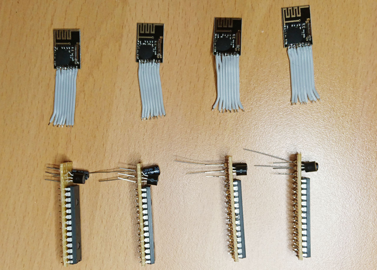
As you can see there are plenty of tiny wires to be stripped, coated with tiny piece of solder and soldered at the right place. Here are µContoller, voltage regulator and nRF24L01:
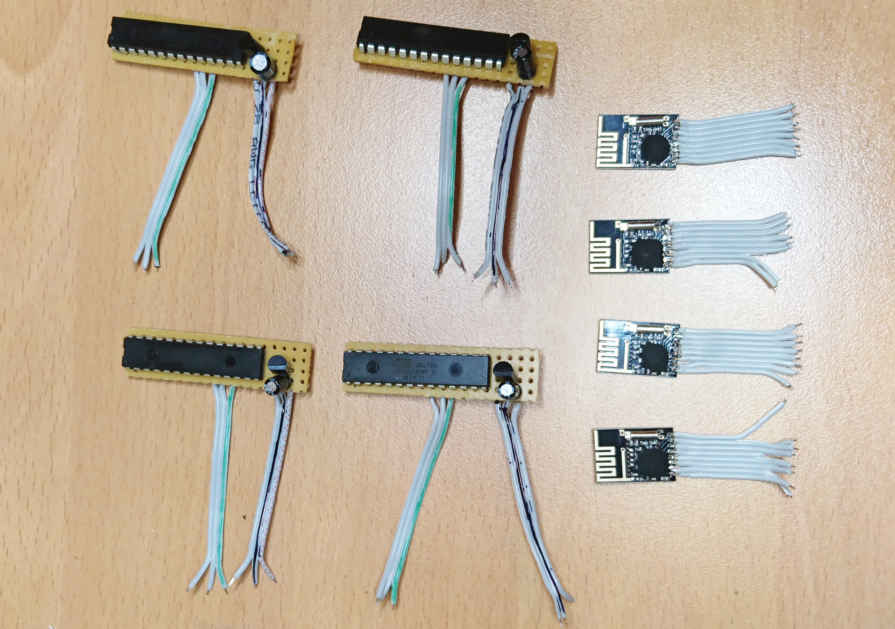
I've completely underestimated the amount of soldering needed for this task:
- 4 x 2.4GHz radio with 8 wires flat cable => 16 times strip the cable, touch the end and 16 times solder each wire ==> 48 operations x 4 => 192 operations
- 4 x 2 3 wire flat cables (one for power to µController and one for control lines) => 12 times strip, touch and solder => 36 operations x 4 => 144 operations
- 4 x 2 wires for VCC and GND on the boards itself => 4 times strip, touch and solder =. 12 operations x 4 => 48 operations
- 4 x 28 pin processor + 3 pin 3.3V regulator + 2x2 capacitors + one jumper between two GNDs = 36s solderings x 4 => 144 operations
- 4 x 4 wires for magnetic sensor => 4 times strip, touch solder => 4 x4 = 16 operations
- 4 x 2 pull up resistors => 16 soldering points
Total: 560 little operations... And some are SMD sized... Currently I think I'm half way through!
Here we have complete mess of all soldered: nRF24L01, H bridge - both soldered to µController's board along with big capacitor and pull-up resistors needed for i²c.
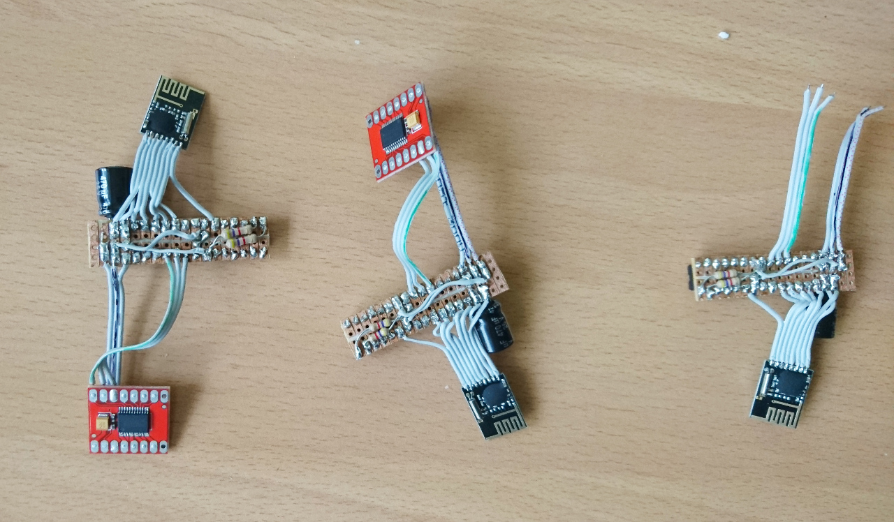
All that is needed now is soldering i²c lines (4 wires for AS5600), wheel hubs positive and negative terminal and tiny motor to H bridge's breakout board.
Comments
Comments powered by Disqus