Power To Wheels, Part II
Transferring Power To Wheels, Part II
When copper rings were in place all that was needed is to make gap between two sides of the ring filled in with solder, sanded smooth down and brushes added.
Of course, it is much easier said than done. And, as you'll soon see, not everything goes as planned (actually this project is riddled with such meandering paths)...
Brushes
Now we have slip rings we need to deliver power to the wheel - make contacts on the outside of the wheel hub. Original idea was to employ brushes for DC motors:
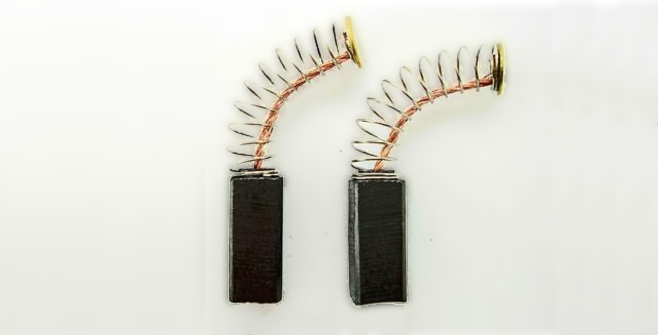
We started with carbon brushes. They slot perfectly into the groove where copper ring sits, have own springs that keeps them pushed against the ring and can be easily and snugly fit to 3D printed holders:
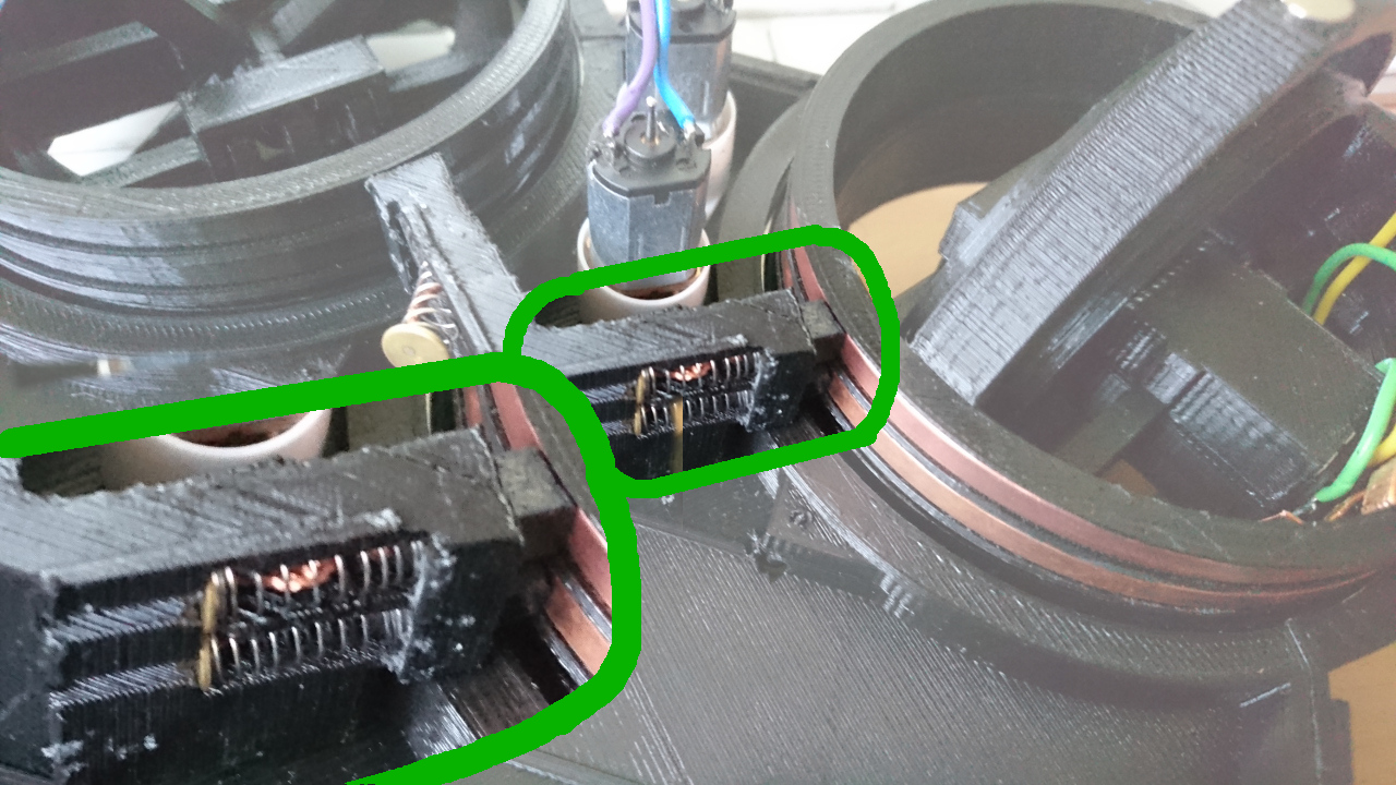
Little Digression
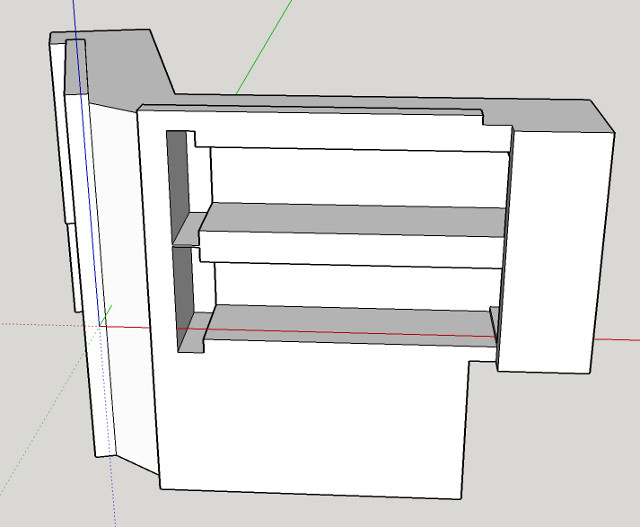
3D printing is a funny business. You can print whatever you want, but not really. As it is in FMD (Fuse Deposition Modeling) there are certain rules that must be followed. For instance - you can always extrude material if it can rest on something. You cannot just print in the thin air! Modern software that prepares 3D models for printing ('slicers') employ a few techniques that fix such situations - add 'support' material where it is needed. Only problem is that since we are talking about 'Fuse' technology, even though such programs deliberately leave certain gap between support and part of the object that is supported, it is never ideal and some material of the support stays attached to the main model. Also, if support is 'standing' on the existing object it is even harder to remove. With small parts like our brushes holder, left picture, the size of the support is proportionally much bigger in comparison to where it stays. In our case there would be gap where the brushes' spring goes. So, ideally we would like support to be used as little as possible. One way to achieve that is to find an appropriate orientation of the object we want to print so it can retain strength(*) and eliminate need for support (or just minimise it). In this case following orientation did the trick:
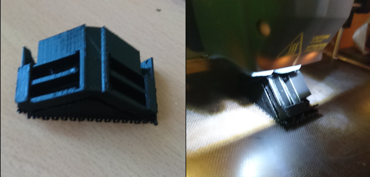
| Note: (*) in FMD 3D printing strength of printed objects, especially with small objects and objects with thin walls, lays along the extrusion lines - not between them |
But...
But there was one little detail that was overlooked in this picture: carbon brushes are made of carbon, more or less similar substance resistors are made of! When measured, resistance of one brush (circuit from brush copper contact to copper ring through the brush) was in the region of about 20Ω . Two brushes twice the resistance. Result, given small metal geared DC motors is that voltage drop inside wheel was around 1/3! On 5V we tested everything, the voltage inside of the wheel was around 3.3V. When powered with 8V (2S) Lithium (LiPo) battery, wheel would get to only 5V. And that's not really enough. The current delivered is proportionally lower, too. So, that was another of the idea which didn't deliver solution as expected hoped for.
Copper Ring Gap
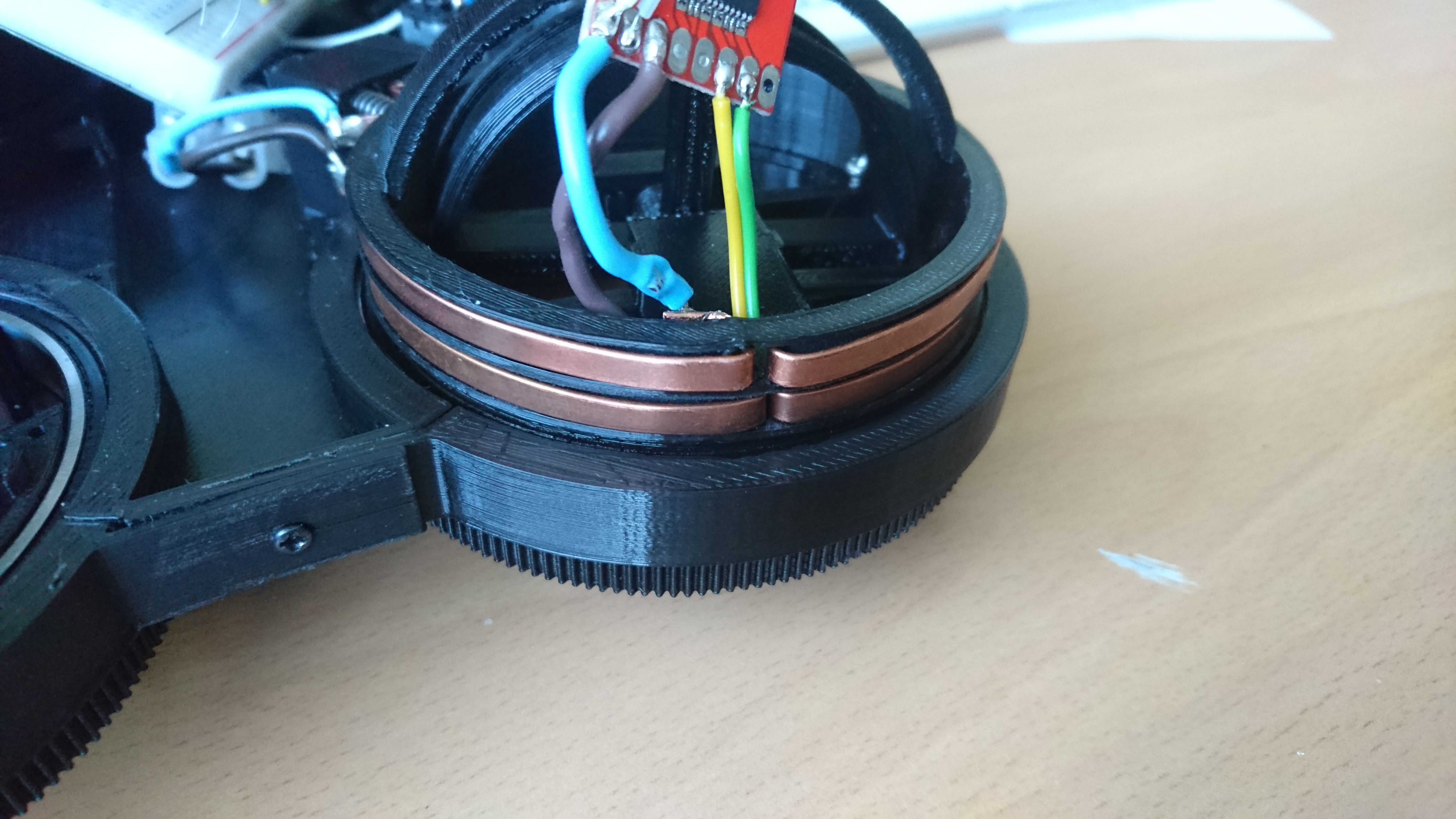
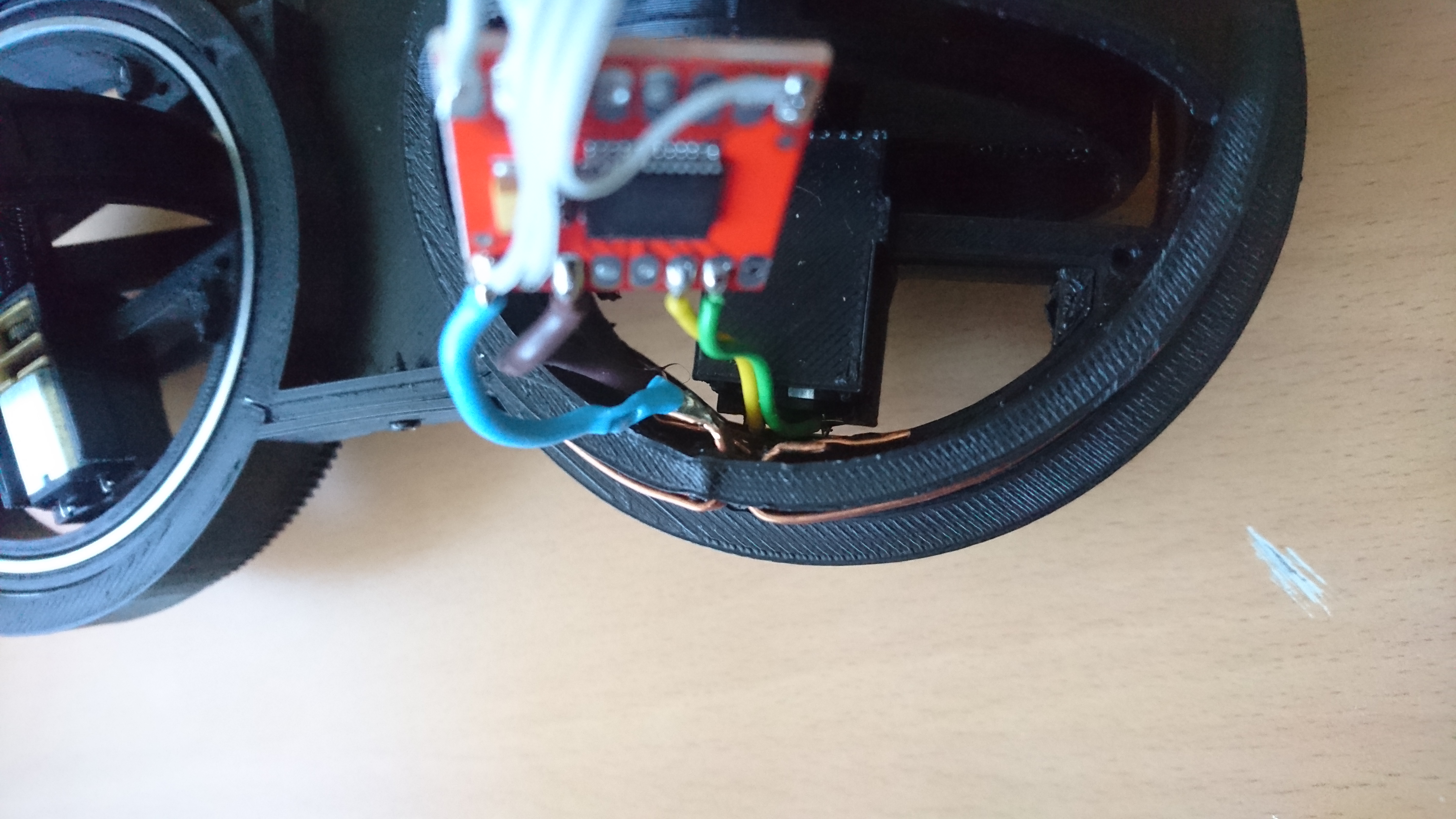
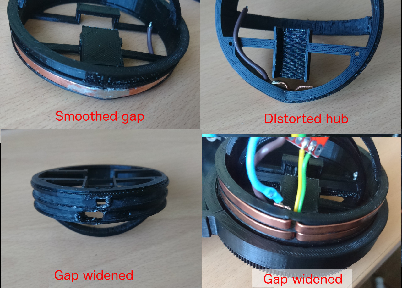
As mentioned earlier the only part of the process that was left to finish our slip rings is soldering two ends and create smooth transition between to ends, tabs pushed through the gap to inside the wheel hub. But, we discovered, hard way, that temperature needed to solder wire to tabs is much greater than temperature needed to melt plastic (PLA in our case, but even ABS has quite a low temperature where plastic becomes soft). Also, even though copper is used to 'disperse' heat (in heat sinks for instance) it is at the same time quite good in conduction it!
Comments
Comments powered by Disqus