Posts about gcc


YFinal Word Before The Competition


Preparation for the PiWars was really fun. Previous competition's anxiety - will we manage to do anything or not didn't affected us this time. It was more - can we prepare to do ALL challenged to the best of our abilities or not.

Rovers

ThreeRovers1

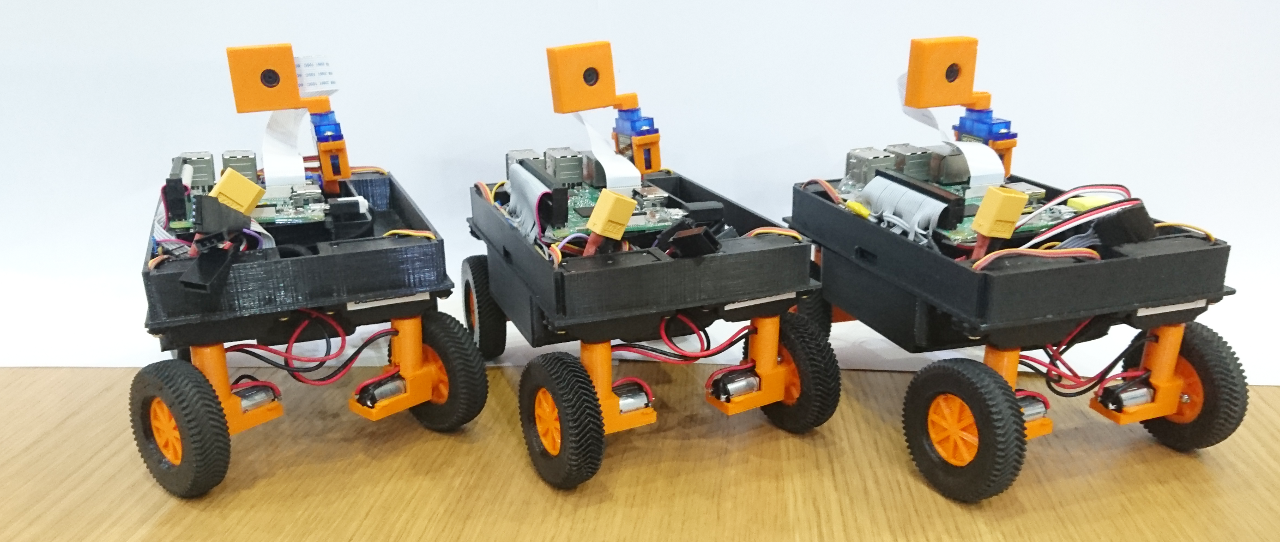
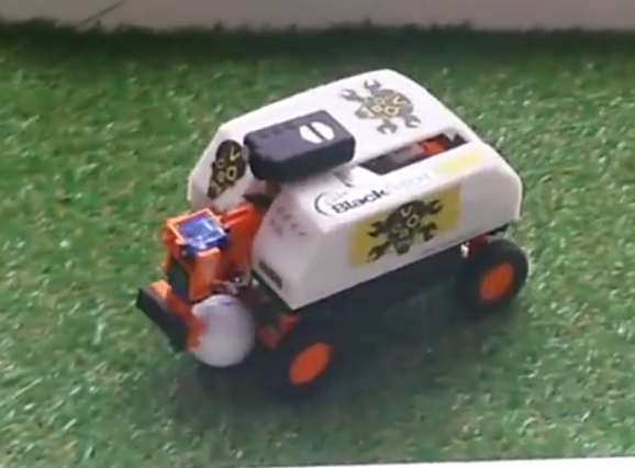
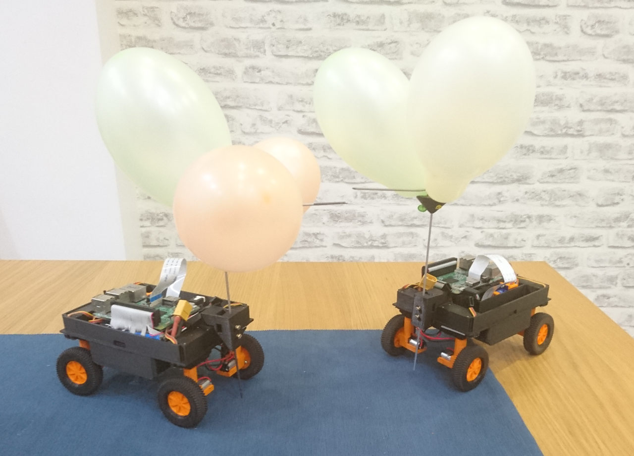
Rovers themselves turned to be really great source of fun and idea of having three for the club worked quite well. That magic number allowed us to have always one spare, one with better motors, one with the latest software (before it was replicated to the others), one with bigger wheels, one we like the best, one that always got one wire to the motor unsoldered somehow, one that had connector wires somehow shorter and harder to use than others, one with broken motor, etc...

At one point only one SD card was really working and then cloned three times. After all, for SF fans: "The Ramans do everything in threes"

Also, it will, hopefully, give us that kind of redundancy we didn't have last time. Last time we had 'preferred' rover (that worked well), one that might be used as replacement, and the 'old' one (with hardware and software lagging). This time all three are up the to job.

Software

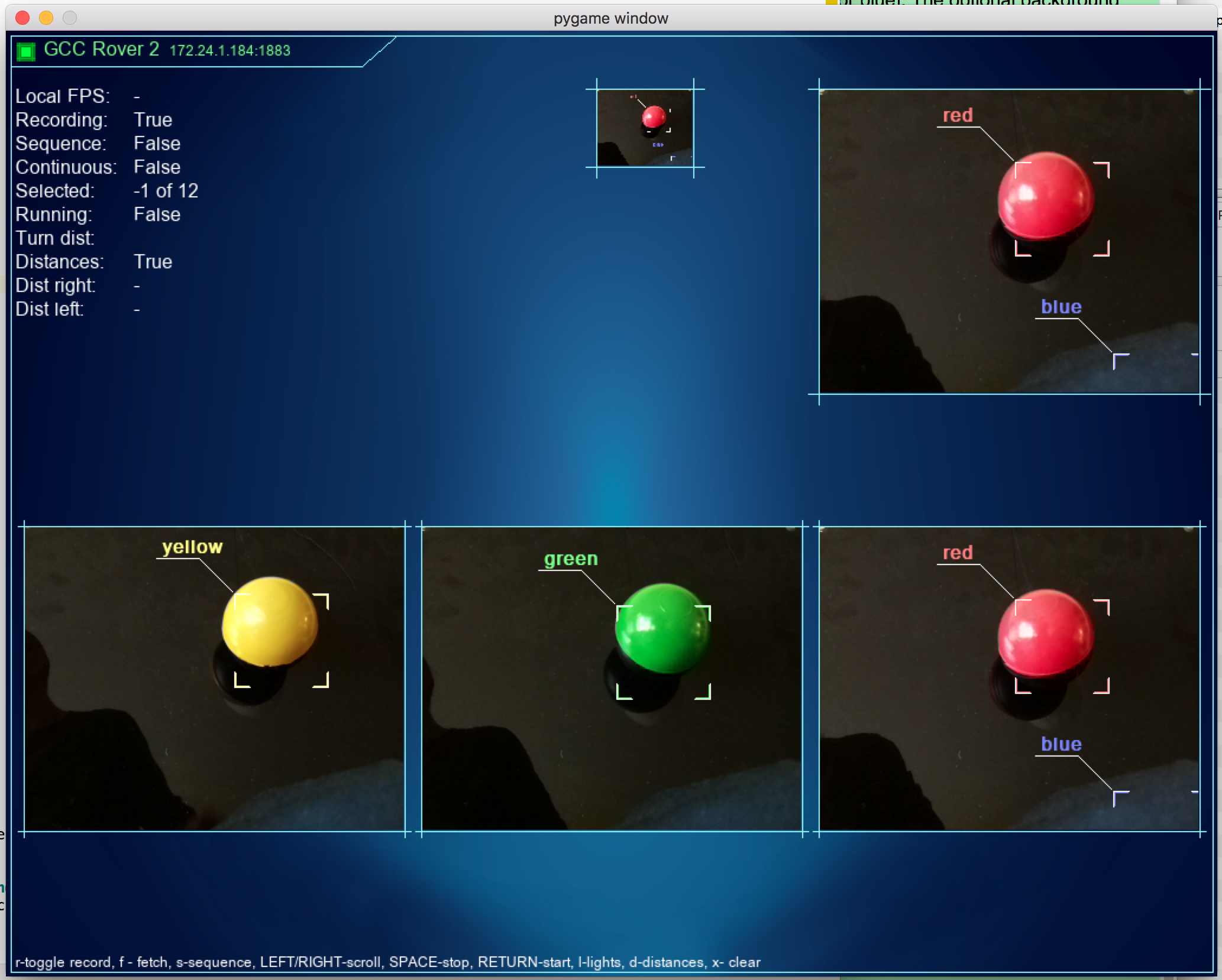
Pyros worked. Worked well in well locally and in school environment. We were able to use and code for rovers from Idle (basic Python IDE) on school computers as well as Unix based OSes (Linux/OSX). There were some issues with message throughput - bugs that were fixed as we have gone along. That particular bug was about limiting number of messages that can be serviced in one iteration of agent's or service's loop. Limit still exists but at least is much higher and we can consider it as 'known problem with a workaround'. And it allowed us to streamline and optimise some other aspects (sending one message for all wheels' speed and orientation instead of 4 for speed and 4 for orientation 50 times a second).

It matured as we progressed through preparation for the PiWars and now we can set up WiFi details through Pyros, read messaging statistic, read storage and the fanciest newcomer - auto discovery rovers using broadcast UDP packets. All our client programs now autodetect existing rovers on the network. How many teams have their rovers discovered like that?

Speaking of client software - a few 'distraction' weekends gave us a new look for our client apps:

accelerometer

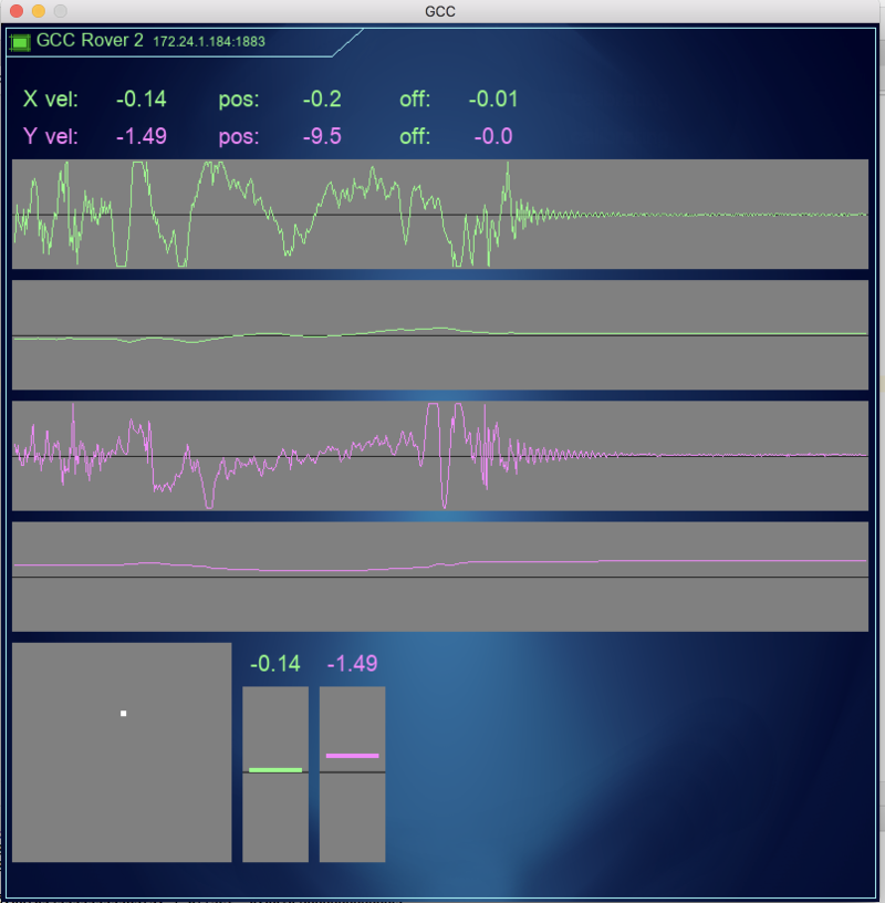
Or blue background and flashy logo in right corner:

flashy-logo

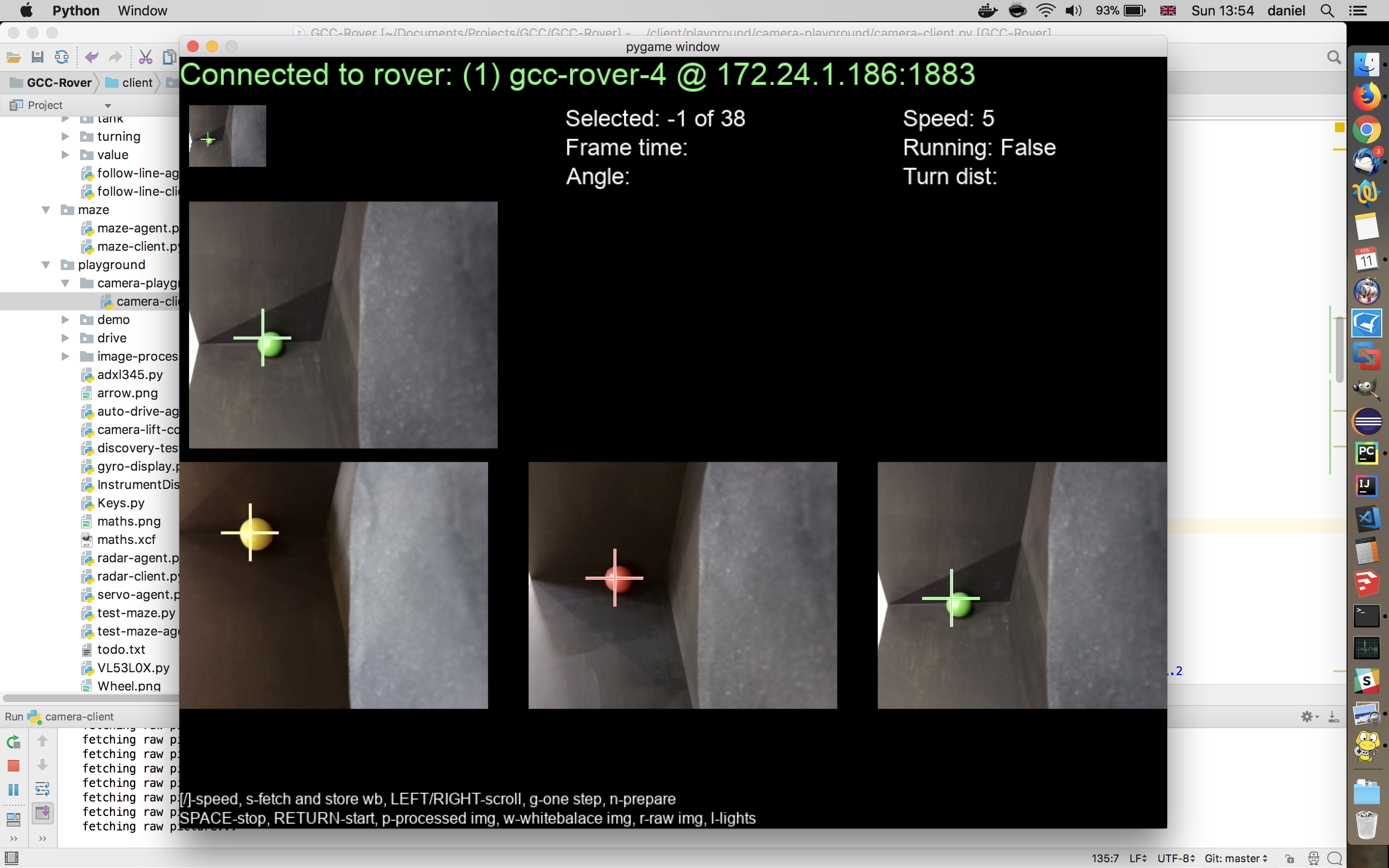
But the most interesting was OpenCV. Shame we didn't start sooner with it. It is completely new area of hours of fun with computer vision and image processing. At first it seemed quite scary and complex, but splitting image to HSV components and analysing them separately, finding contours, finding contours' properties as area and diameter, applying them as masks to hue channel and doing histograms, drawing 'debug' pictures and shapes - all of it on its own was worth going to PiWars.

Also, it is worth mentioning that we managed some of the stuff we failed to implement last time. For instance - making lunge attack and orbiting around opponent.

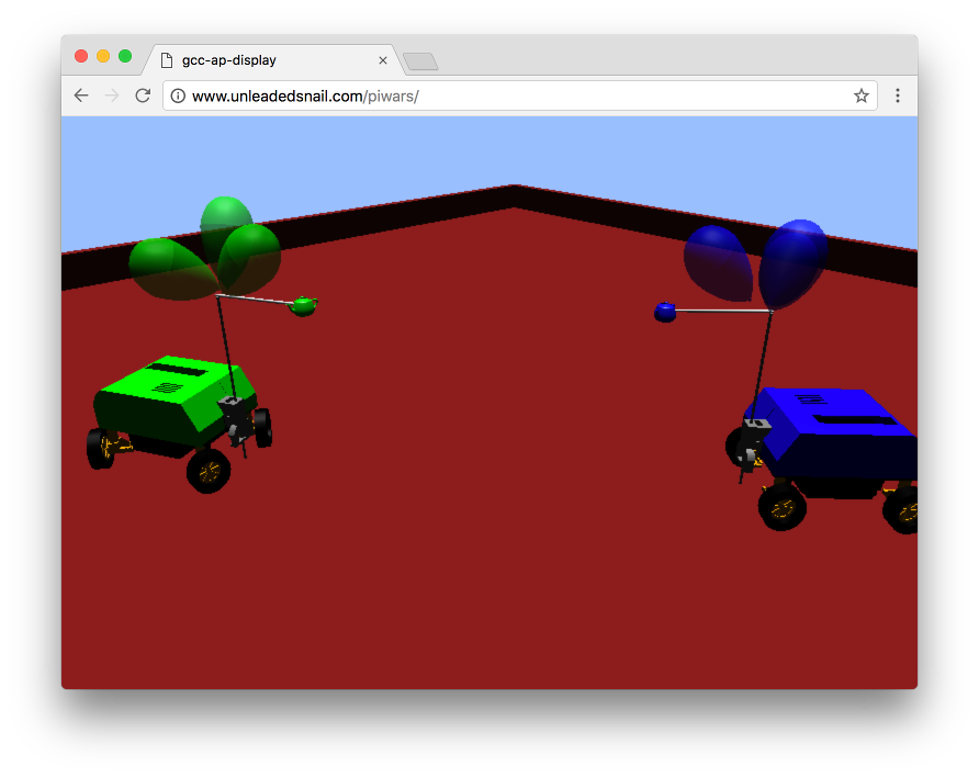
When talking of distractions - this was the something completely different and yet PiWars related. Our club member David did online PiNoon interactive game!

VirtualArena4

Given more time I am sure it will grow to be properly online so people can battle one against another (not only on the same computer as it is currently).

Hardware

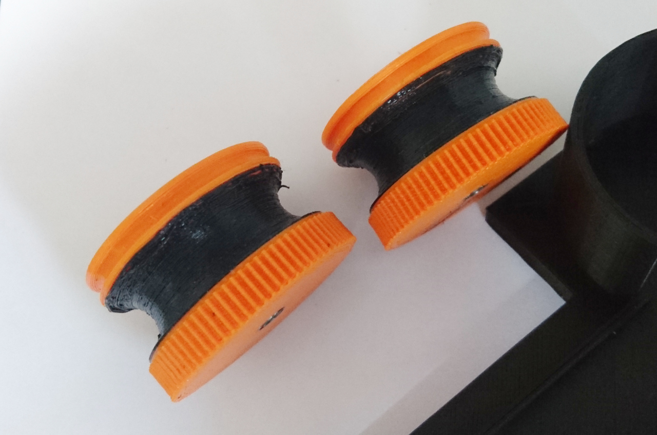
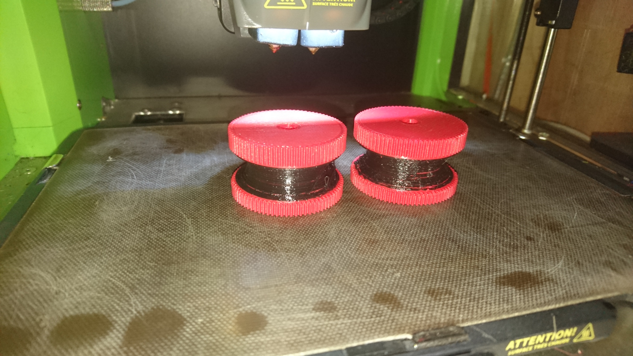
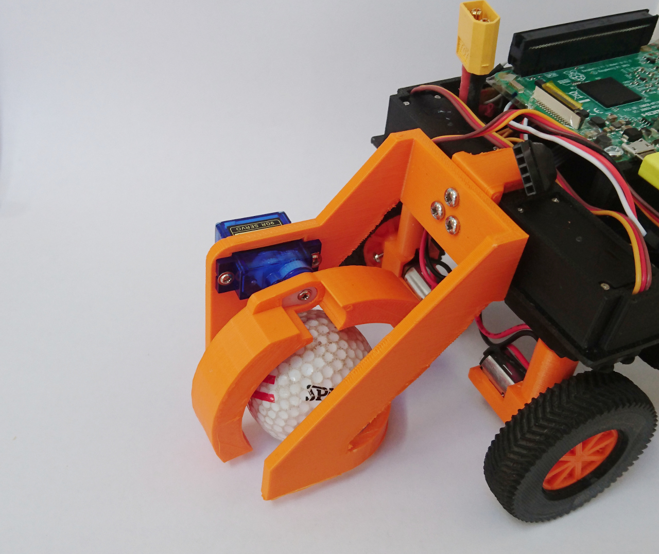
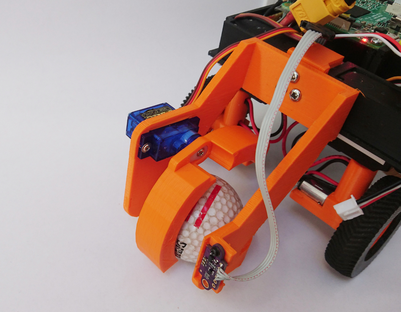
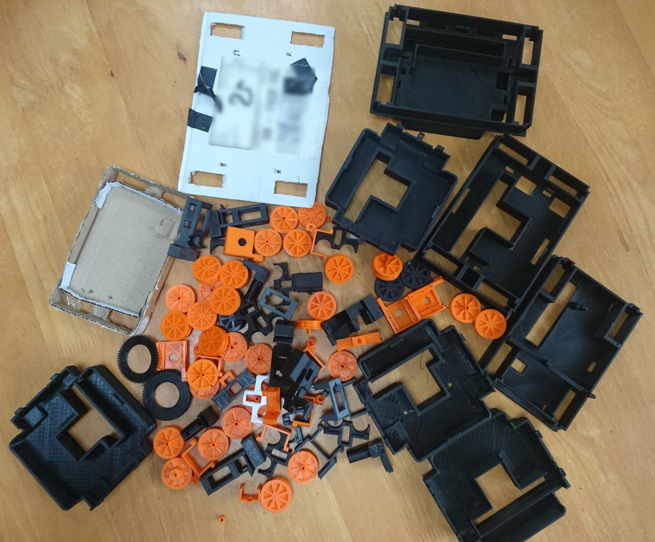
This time we didn't do as much as last time - our rovers were already built and ready (more or less). Making golf ball catcher and minor improvements to existing bits and pieces (PiNoon holder and VL53L0X sensors holder) were less exciting in comparison to the Nerf gun! It required engineering (and we again used Sketchup for our designs - luckily provided on the school computers, too). Also it was really nice seeing frowns on some student faces not understanding how two rotating cylinders can do the job - to broad smiles when we finally spun it up. I am sure the moment we go through The Duck Shoot challenge there'll be unapproved software tinkering to increase motor speeds - just for fun! Oh, and I hope we didn't leave a lot of mess behind us in the classrooms we used for our club.

Same as for the previous PiWars we did lots of 3D printing, too. CEL's Robox 3D printer was put through the test. I am sure I did a few hundred of hours of printing for us. Last year dual material head developed problem which was, after all, quickly sorted out by CEL's engineer. So this time we had a spare head. And for a reason (same old head developed same old problem this time, too). Also, ability to print two materials next to each other (flexible ninja flex and PLA/ABS) helped some things...

Support And Sponsors

Same as last year, it is worth mentioning that our club had support from a few of companies:
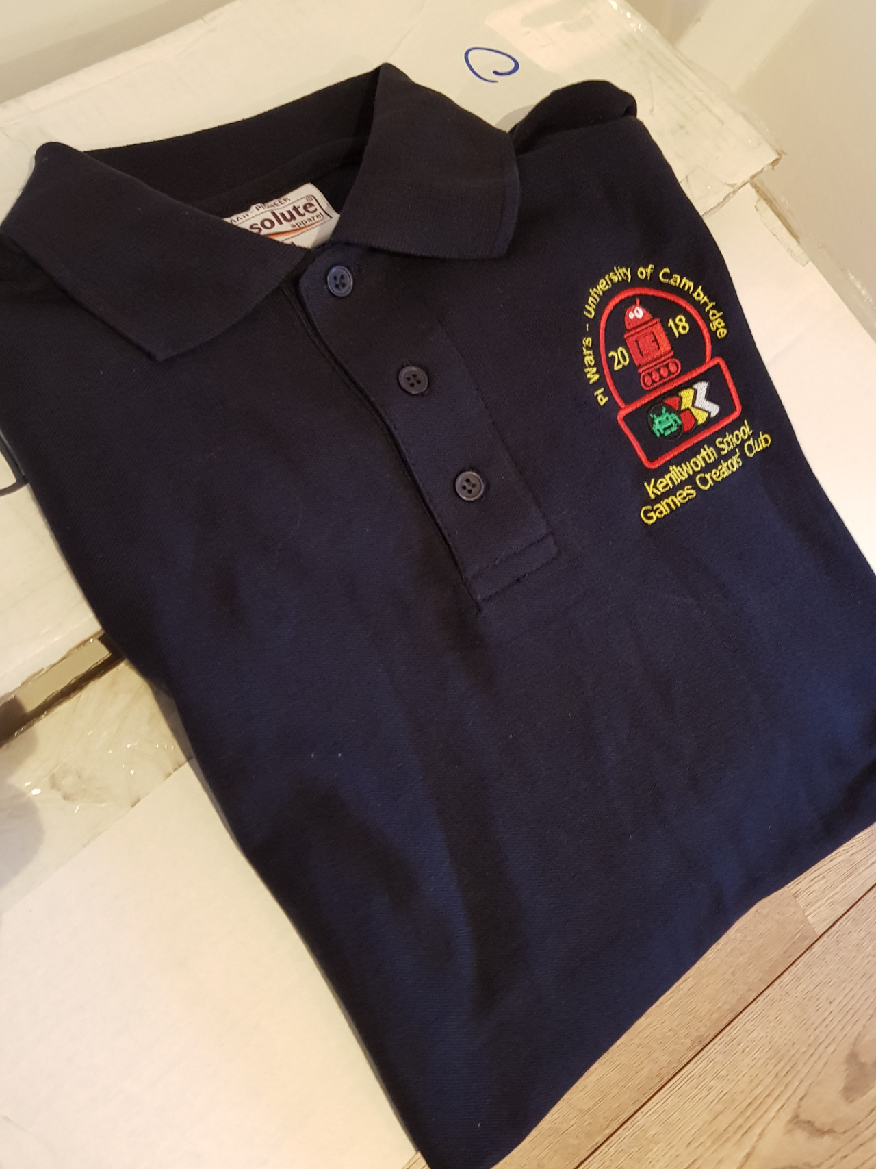
polo-shirts-2018

Vevectric-logoctric originally sponsored one rover (it is still going!) and this time provided our team with T-shirts for the day. Also, we always new if we needed any CNC and/or 3D printing we would go to them!

BlackPepperLogo
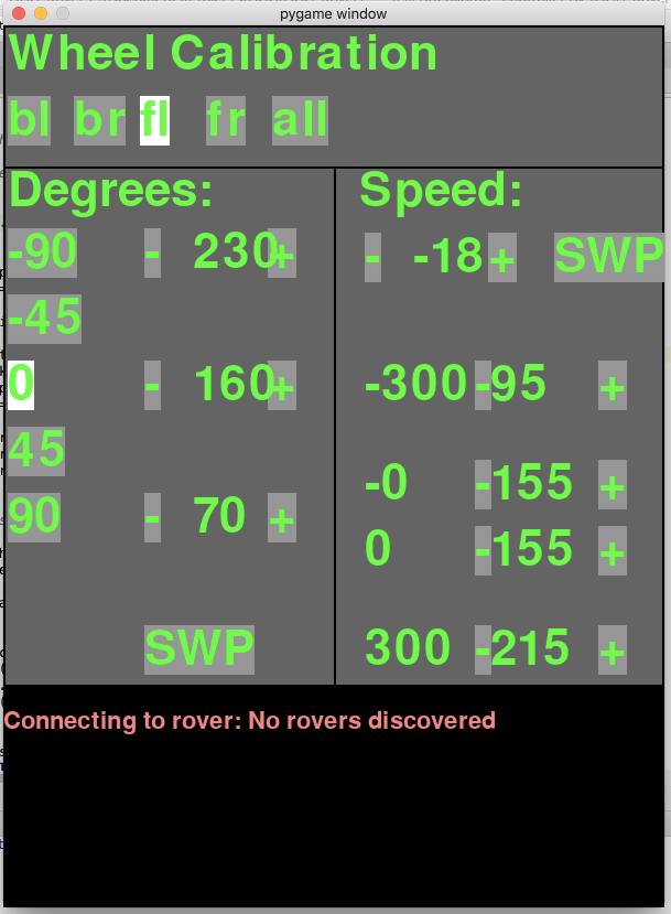
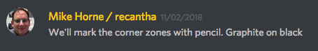
Black Pepper sponsored other rover last time (now completely upgraded) and gave us all the needed support this time (even pledging money or parts when needed). Black stress balls they passed over worked as holders for Somewhere Over the Rainbow balls. And we shouldn't forget the famous 'Rover Calibration Unit' they paid to be printed:

[gallery ids="1311,1310" type="rectangular"]

creative-sphere

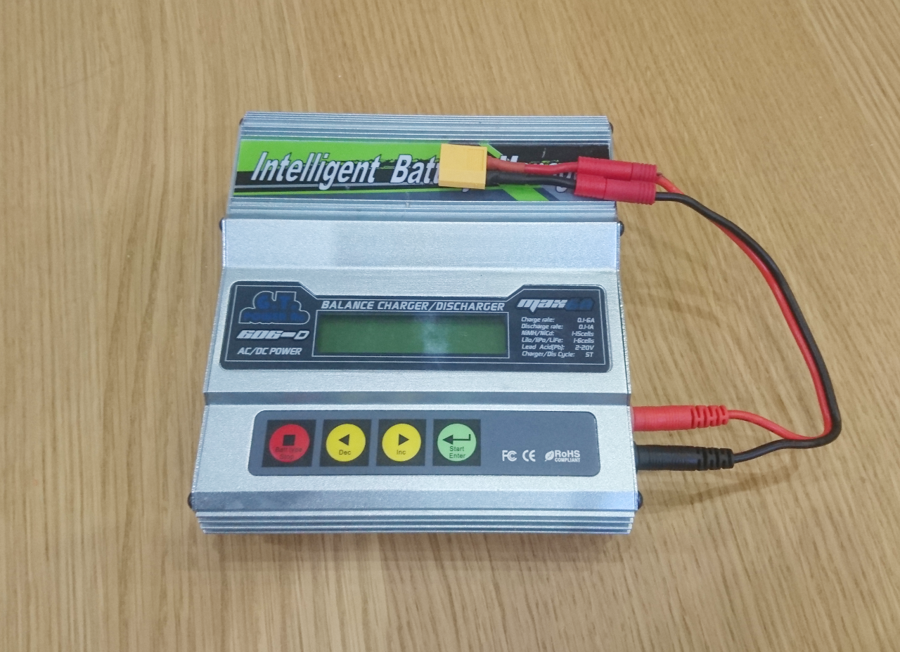
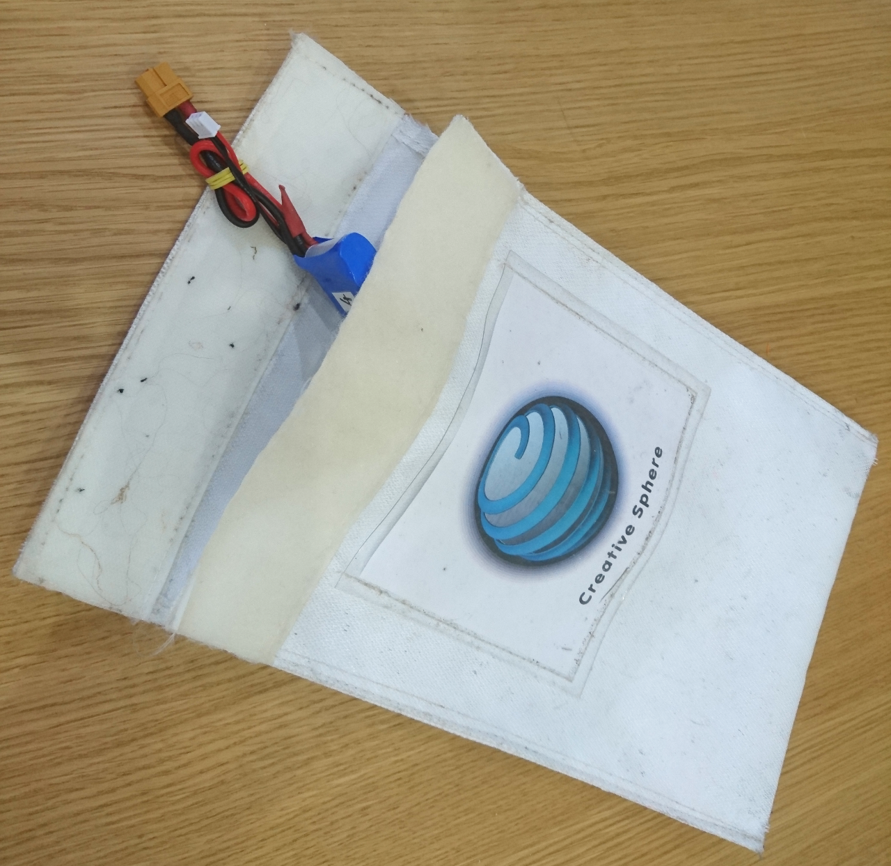
And least but not least, Creative Sphere funded 3D printing (filament and otherwise) and some small bits and pieces (for instance extra servos/ESCs, ATmega328p chip for ultrasonic sensors or upgrade of 9 axis sensor mpu9250).

Aside of those companies, we must mention some parents for their support - especially Mujeeb Parambath that supported us not only morally but materially donating money for another couple of distance sensors and PS3 bluetooth controller.

Lessons Learned

Don't leave the hard parts for last. Do computer vision sooner (because it is fun). Rewrite code more often (is it in Agile manifesto or close to it?). Start preparations before Christmas - not after.

But not all lessons were on our expense. For instance - always have spare parts (read: servos) worked well as we have broken a couple in a process of practising for the PiNoon challenge. Have options open - we decided to stick with infrared ToF sensors over ultrasonic due to extra time we needed to make them work reliably in the first place.

See you all on Saturday!

YAnd Finally - The Magic Maze


The Minimal Maze challenge was one we did first last year, ahead of all other competitors, on the day last year and in two goes we did relatively well. Of two goes one was clean run and one was abandoned due forgetting the rules in our excitement (we could have saved it and lost some points but score much more).

This year we left the preparation for the challenge as last. And you'll understand in a minute why! Previously we did it using one ToF sensor (VL53L0X) attached to the servo and starting at 45º to left. The idea was to scan distance from the side and front. And it worked well - rover was going through the corners quite nicely (aside of occasional overshooting or crashing straight on). It was funny watching it avoid the walls at the last possible moment! When the sensor is to detect a sudden opening in the left wall, it would switch to three steps:

  1. turn sensor to 90º - directly to the wall and wait it pass past rover
  2. turn 180º (not really sophisticated as it was time based)
  3. turn sensor to the right (at 45º again)
Now we have two sensors and, again here is picture of their arrangements:

sensors2Left and right orientations are exactly what we needed this time.

Also, from Somewhere Over the Rainbow challenge, we have following the wall algorithm which was ever so slightly changed here. Instead of stopping when front sensor detected getting close to the wall, we will do turning - away from the wall. Condition for it would be distance of the front sensor to the wall (taking in consideration measured speed as delta offset of previous and current reading of the front distance).

That way our rover can just stick to the left wall, turning to the right, away from it when too close, until it gets to the end. This condition is very similar as in previous year's algorithm: when distance between rover and left wall becomes greater than corridor width(*), that means we are in the middle of a turning and we can then just simply switch from hugging left wall to following right wall and continue until out of the maze. Simple, isn't it?

(*) Corridor width is important and is measured before the run. Sensor scans left and right distances and adds them up to calculate corridor width and then halves it to get 'ideal distance' from a wall (left or right).

This time the simplicity of algorithm won over all other ideas. Well, unfortunately there are still lots of 'moving' parts and gains and noisiness of distance sensors so we cannot still run through the maze at the full speed. If we had another three-four weeks...

YStraight Run Challenge


Last year we had one out of three attempts on the Straight Line Speed Test challenge. Now, in a hindsight, we can blame the gyro or our lack of gyro feedback. It is so easy to spot when the mean value of every oscillating, noisy gyro is not quite on. The accumulated value tends to creep to one side. Repeated calibration usually is way to sort it (or maybe better calibration routine we never got to use).

This year we decided to do it using distance sensors. And WAY faster motors! :D

Unlike using gyroscope, distance sensors are slower but over time more accurate. At least that's a theory. Remember our distance sensor's configuration:

[gallery ids="1113" type="rectangular"]

Middle, 45º orientation is perfect for this challenge. All we needed to do was to read both distances and apply steering depending on the difference of those distances.

error = distance2 - distance1
if abs(error)  steerMaxControl:
    controlSteer = steerMaxControl
elif controlSteer < -steerMaxControl:
    controlSteer = -steerMaxControl

leftAngle = int(-controlSteer)
rightAngle = int(-controlSteer)
..

And results were promising. No bananas were (significantly) harmed during filming this video:

YOur Take on OpenCV (for SOTR Challenge)


OpenCV is fun. It looked scary before we tried it but when we did, it turned out to be much easier than we anticipated. Shame we didn't start with it sooner (and by sooner I mean for last year's competition). Our rovers were equipped with Raspberry Pi cameras since day one. The idea was to use them for follow the line challenge, for recording and first person driving - none of which really worked well due to lack of time to spend on it. Now, for the Somewhere Over the Rainbow challenge, we finally made a use of it!

Setting Up the Picture

We read a few tutorials online and decided to go with an HSV picture as a base for image analysis. Our rovers have a camera service that delivers 'raw' byte data of an image in RGB format directly from the camera and delivers it to all interested parties over MQTT. That allows us not only to break the code to smaller chunks and make services where code provides access to hardware or software resources, but also to easily implement a monitor of what is really happening to the rover at any time.

So, as soon as we receive image we prepare it to be used in OpenCV:

pilImage = toPILImage(message)
openCVImage = numpy.array(pilImage)
results = processImageCV(openCVImage)
...

Next is to blur image a bit and convert it to HSV components inside of OpenCV:

blurredImage = cv2.GaussianBlur(image, (5, 5), 0)
hsvImage = cv2.cvtColor(blurredImage, cv2.COLOR_RGB2HSV)
hueChannel, satChannel, valChannel = cv2.split(hsvImage)

pyroslib.publish("overtherainbow/processed", PIL.Image.fromarray(cv2.cvtColor(hueChannel, cv2.COLOR_GRAY2RGB)).tobytes("raw"))
pyroslib.publish("overtherainbow/processed", PIL.Image.fromarray(cv2.cvtColor(valChannel, cv2.COLOR_GRAY2RGB)).tobytes("raw"))
pyroslib.publish("overtherainbow/processed", PIL.Image.fromarray(cv2.cvtColor(satChannel, cv2.COLOR_GRAY2RGB)).tobytes("raw"))

HSV

Finding Contours

The following step was one of the most important that we spend lots of time on tweaking, but at the end, the solution ended up relatively simple. Also, recompiling OpenCV with NEON and FVPV3 optimisations helped - a lot!

The problem is finding the right channel to apply the threshold and the right threshold value to nicely select the balls on the black background. The main issue was that with lots of light, the saturation channel was quite noisy as colour was found everywhere, while the value channel was really nice. In lower light conditions, value channel was not that useful, while saturation channel was jumping up and down yelling 'pick me'!

The algorithm we used goes something like this:

  1. combine saturation and value channels with some weights (current values are: 0.4 for saturation and 0.6 for value)
  2. start with value for threshold of 225 (25 less of 250 which is nearly at the top)
  3. find contours
  4. sanitise contours
  5. check if the correct number of contours was detected (i.e. more than 0 and less than many)
  6. if not, drop the threshold value by 25 and repeat from step 3

With that we can see slowly how  ball is forming at the middle of the picture.

Here's the code:

gray = sChannel.copy()
cv2.addWeighted(sChannel, 0.4, vChannel, 0.6, 0, gray)

threshLimit = 225
iteration = 0

while True:
thresh = cv2.threshold(gray, threshLimit, 255, cv2.THRESH_BINARY)[1]
iteration += 1

cnts = cv2.findContours(thresh, cv2.RETR_EXTERNAL, cv2.CHAIN_APPROX_SIMPLE)
cnts = cnts[1]

initialCntNum = len(cnts)
sanitiseContours(cnts)

pyroslib.publish("overtherainbow/processed", PIL.Image.fromarray(cv2.cvtColor(thresh, cv2.COLOR_GRAY2RGB)).tobytes("raw"))

if 0 < len(cnts) < 6:
  log(DEBUG_LEVEL_ALL, "Found good number of areas after " + str(iteration) + " iterations, contours " + str(len(cnts)))
  return cnts, thresh

if threshLimit < 30:
  log(DEBUG_LEVEL_ALL, "Failed to find good number of areas after " + str(iteration) + " iterations")
  return cnts, thresh

threshLimit -= 25

As you can see finding the contours was already a given function of OpenCV. Here are the steps our rover did finding green colour:

SOTR-Iterations

Sanitising Contours

We know we are searching for a ball. Round contour. Or something that looks round to human eye. Even young moon looks quite round as our brain fill in the gaps. And that problem of a young moon - area of the ball where too much light reflects or where there is not enough light is preventing us to use simple a 'find circle' in each contour. So, we went on checking contours radius (radius of minimal circle that can be drawn over the contour) and area:

for i in range(len(cnts) - 1, -1, -1):
  center, radius = cv2.minEnclosingCircle(cnts[i])
  area = cv2.contourArea(cnts[i])
  if radius = 128:
    del cnts[i]

Since our camera is at the back of the rover, the lower half of the picture is the rover itself, so all contours at that area are immediately ignored (centre > 128).

MIN_RADIUS, MIN_AREA and MAX_AREA are fetched from real life running of the code for a given resolution, position of the camera and rover given size of arena, etc... And a fudge factor of 0.7!

MIN_RADUIS = 8
MIN_AREA = MIN_RADUIS * MIN_RADUIS * math.pi * 0.7
MAX_AREA = 13000.0

Processing Results

After we have found contours on the picture we needed to find a colour of area of the contour. First we use contour to make a mask and apply it to hue channel (only look at the pixels inside of the contour.

Now the colour itself. Seems easy but it wasn't. Remember the young moon? Our brain immediately makes it into a full circle - filling in the gaps. If a ball is recognised for less then half of the area of the circle, and colours vary (red and yellow are quite close to each other) it is a problem finding out what exactly the colour is. Taking average skews the results so we decided to take a histogram of all colours and pick the most predominant. And it seems to be working well:

mask = numpy.zeros(hChannel.shape[:2], dtype="uint8")
cv2.drawContours(mask, [contour], -1, 255, -1)
mask = cv2.erode(mask, None, iterations=2)

maskAnd = hChannel.copy()
cv2.bitwise_and(hChannel, mask, maskAnd)

pyroslib.publish("overtherainbow/processed", PIL.Image.fromarray(cv2.cvtColor(maskAnd, cv2.COLOR_GRAY2RGB)).tobytes("raw"))

hist = cv2.calcHist([hChannel], [0], mask, [255], [0, 255], False)

value = numpy.argmax(hist)

if value  145:
  return "red", value
elif 19 <= value <= 34:
  return "yellow", value
elif 40 <= value <= 76:
  return "green", value
elif 90 <= value <= 138:
  return "blue", value
else:
  return "", value

Here it is when colour is spotted and mask applied to the hue channel:GreenFinal
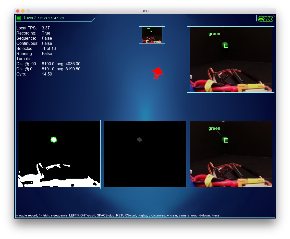
The left image is of the found contour, middle of mask applied to the hue channel (see above what hue was looking like as complete) and last image is the result... well, for looks!

The rest is for the main Somewhere Over the Rainbow agent to process the recognised colours. When there is only one we take it as it is. When there are more than one coloured balls recognised we check if any of them are red and if so discard them as they are usually mainly from the noise of the background. If still undetermined - we take more pictures and process more. Speaking of red - red and yellow we take multiple takes of reading picture as camera's adaptive lighting can change over several frames and produce better results. For green and blue this are far more deterministic...

Here it is when all was put together:

YSomewhere Over The Rainbow Analysis


The Somewhere Over the Rainbow challenge is new this year and one of the most interesting. We started by breaking down what the rover needs to do for it in simple tasks/steps (no matter how complex each step is):

  • turn round the arena at 90º steps (starting with initial 45º turn) - but we need 135º and 180º turns, too
  • scan the colour of a ball that that rover is facing
  • going towards a corner
  • follow left or right wall of the arena to an adjacent corner
sotr-analysis

Turning around

In Somewhere Over the Rainbow there are several precise angles that the rover should turn:
  • 45º at the beginning of the scanning phase
  • 90º for scanning each new corner or to visit the next corner
  • 135º when facing a corner and needs to go to the adjacent corner on the left or the right
  • 180º when visiting the opposite corner
The first (45º) angle is always to one side while the other 90º and 135º are in both directions. For 180º is really doesn't matter which direction it is executed at. We've tried to implement it using internal gyro and PID algorithm. 'P' component says how quickly it should turn, 'D' component dampens it down if it start moving way too fast while 'I' component is giving us a 'nudge' when we are close to the target and speed (PWM percentage) is not enough to really drive motors. When 'D' component is relatively big, 'I' is not collected (reset to zero), but the moment 'D' falls below certain threshold we add errors for 'I' component and it allow us to continue moving when the power could be low

Scanning for Ball Colours

Scanning for ball colours step is 'simple': turn 45º, fetch the colour of the ball we face (and add the first letter of the colour to a string), turn 90º, scan, add to string and repeat. Doing it four times should give us 4 different colours and from the order we can deduct the following steps.

Now, the 'simple' task was originally done by counting RGB pixels and sorting them as red, green, yellow and blue, but that method itself turned to be quite simplistic and not reliable enough. The next blog will explain more about how we used Open CV...

Finding Nemo

Finding a corner is another small autonomous challenge we've done. To do so our V formation of distance sensors works like a charm:

sensors2

On the picture above we use the middle configuration for this process. The left and right sensor should return a similar distance. If not rover will drive at an angle which would balance distances. Our rover can continue to 'look' forward while driving to the left or right (strafe at some degree). Amount of 'strafe' (angle at which all wheels are going to be) is directly proportionate to proportion of distances of left and right sensor. When left squared distance plus right squared distance is squared target distance (let's say 120 or 150mm) then we've got quite close to the corner. A PID algorithm is responsible for our rover to not slam into the corner nor stopping way too soon. That algorithm will dictate the speed of the rover.

Following Walls

The last piece of the puzzle is following left or right wall. If the next ball is in corner that is left or right to the current corner, the rover just needs to turn 135º and follow the wall. In configuration above it will be one on the left or right. One sensor will be used to judge the distance from the wall and one distance from the corner (opposite wall). The forward sensor will be used with a PID algorithm as above to calculate the speed of the rover. The side sensors will tell us what the rover is supposed to be doing:
  • if delta distances (current distance minus previous distance) are close to zero (some small number) rover will continue with driving forward gently strafing to adjust to asked distance from the wall (120 or 150mm).
  • if delta distances are increasing - that would mean that rover is going away from the wall and corrective action is needed. That corrective action is calculated as following:
    • front sensors deltas will determine rover's current speed and with that speed we can calculate distance rover will travel for one pass of the loop (~ 0.1s as that much it takes for vl53l0x to calculate distance)
    • rover will rotate around a point that is a the side of it so circle's arc is of length of calculated travel. That would mean rover will adjust direction so it is parallel to the wallturning-maths
  • if delta distances are decreasing - that would mean rover is going towards the wall and similar action as above is needed but around the point at opposite side
With that we can assume by the time the rover arrives to the corner, it will be adequately parallel to the wall no matter which angle it started from. Since the gyro is not absolutely correct (they have a bad tendency to drift) this step is were we expect to correct accumulated errors.

Putting It Together

With the above steps now we can do the challenge.

First we'll turn 45º to face first ball. Then scan, turn 90º and repeat three times to collect all corner colours. If any corner colour is inconclusive we'll put 'X' in the list.

If there are 'X' characters in the list we can turn again to those corners and re-do the scanning until we can determine four distinctive colours. The idea is that if we get two of the same colours out of four - we can just invalidate both and re-scan those corners.

Using OpenCV we can even find the 'moment' (centre) of the ball and adjust required angle to move to the next corner.

When the colour of the balls are determined we need to rotate to the red (shifting our string of colour's first letter accordingly). As a result we'll have a string that always starts with 'R'.  Analysis gave us 6 distinct combinations as following:

sotr-analysis1

The strings are: RGYB, RBGY, RYGB, RGBY, RBYG or RYBG only! And those 6 combinations can be translated into series of 'find corner'; turn -135º, -90º, 90º or 135º; follow left or right wall! Just as described below. Here are those steps:

sotr-analysis2

Simple, right?

YLight Armoured Mobile Nerf Cannon


Finally got a short break between tinkering with OpenCV, complaining about sensors and fine tuning the rover logic for Somewhere Over the Rainbow challenge to write up about our take on the Duck Shoot challenge.

We started with and with very limited knowledge about Nerf guns. The only thing that was provided for the club were five packs of Nerf darts so we had some idea of the size we needed.

The idea was to have two concave cylinders with gears on bottom and a grove on the other so some kind of belt (elastic band) can be used to turn them). gun-1 
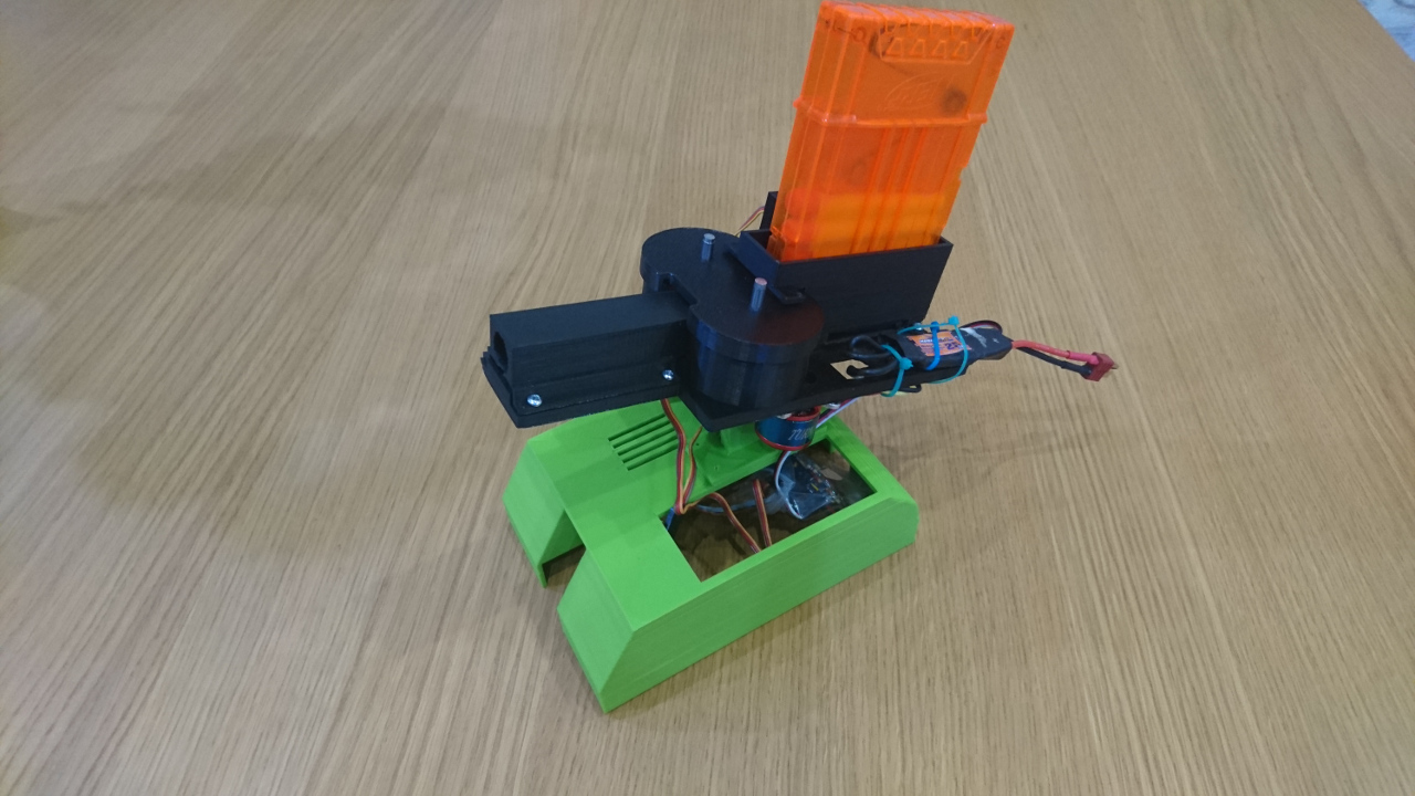
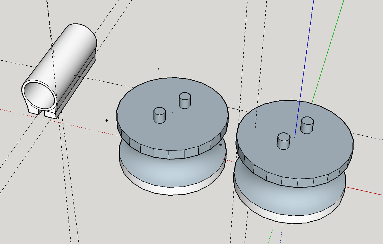
The nerf dart would be somehow delivered in between two spinning cylinders and would be then propelled forward through the barrel. We started with designing a concave cylinder in Sketchup first as it seemed to be hardest challenge of all. Fortunately it wasn't half as hard as we thought.

Next was to create a gear at the bottom of the cylinder. There even was a simple gear making plugin for Sketchup available. It turned out to be slightly a longer exercise as one of the options was to use RC brushless motor (with ESC to drive it) with existing pinion. That  pinion's gears are standard gears with MOD of 0.5. This made us have to learn about engineering and gears a bit so we don't end up stripping the teeth on our 3D printed gears. Even half a millimetre discrepancy would be disastrous.

gears

Luckily we stared with cylinders of exactly 40mm diameter, which by the formula (N = PCD / MOD) turned out to need 80 teeth exactly (40mm/MOD 0.5 = 80 teeth).

Since we have access to a 3D printer that can print two materials at the same time (CEL Robox) of which one can be flexible (ninja-flex). We went one step further and designed our cylinders to have a 'coating' of the rubbery ninja-flex material on the inside of the concave part - for better grip! Here is first prototype of it:

theduckshoot-gears-1

Next was to put all together: feathering shaft of 250 size Align clone helicopter with bearings, big slab of plastic and top housing and here is our first go at The Duck Shoot:

[gallery ids="1276,1278" type="rectangular"]

Power is 2800KV brushless motor which we still didn't drive a the fastest speed in fear of stripping gears heating would soften the plastic (first prototype was done in PLA). Initial results were phenomenal:

Next was to mount it on to the rover. We kinda rushed this bit...

We printed gears in ABS with and dropped grove at the top:gears-robox

Picked the biggest servo we have to move whole contraption up and down and quickly designed mount for it:mount1

Added made adapter for existing nerf gun magazine (only cheat) and feeder driven by a servo:

Printed another 'top' for the rover - this time with 0.5mm thicker walls and mounted the whole lot on in:

complete-top

The wiring of two servos and an ESC was a small problem mainly because our robot only has two 'spare' servo connections provided by the Raspberry Pi while all three would need servo signal to drive them. Fortunately, in parallel with this we were developing three sonar sensors + two servos i2c enabled breakout board. Those two extra servos slotted in perfectly in the mixture.

And as a chery on the cake came the code in our jcontroller service which controls not only elevation and trigger servos, but speed of the cylinders, too!

At least with all above we were able to say: 2 done, 5 more to go!

YVirtual PiNoon?


With one challenge sorted, and a few more on the way, we have decided to take a little moment, and make a game - we aren't called the Games Creators Club (GCC) for nothing! With only weeks left, we should have been focusing on the other autonomous challenges, and other challenges that we are far from completing, but instead, we made this:

GCC Virtual Rover PiNoon!

piwars Click on above image to try out virtual PiNoon with our rovers!! Keys are:

  • 'ASDW' for movement and 'Q' and 'E' for rotation of the green rover
  • 'JKLI' for movement and 'U' and 'O' for rotation of the blue rover
  • Space is to start

Technology

Since all rover parts are 3D printed we could just use the 3d model files that we used, and directly add them to the game. With a bit of scaling, and positioning, we could easily implement the whole rover!

The GCC Virtual Rover is made using Java and the LibGDX framework giving us immediate access to many different platforms including desktop (Windows, Linux and OSX applications), Android (soon to come to the Play store near you), iOS and HTML5 (as seen above). Also, due to circumstances, we are involved in the Raspberry Pi 'fork' of LibGDX as well - so expect the above game to work on RPi at full speed as well, even on a PiZero!)

The HTML5 is delivered (by LibGDX) using GWT - which is Java compiled to JavaScript. The game itself (through LibGDX) is made in Open GLES which, in a sense, is compatible with WebGL. We have tried game on Firefox and Chrome on Mac, and Chrome and Edge (shudder) on Windows, but it should really work on all modern browsers.

VirtualArena4.png An earlier version of the game, still with graphical glitches!

The game's source is in the github, but, please, be gentle as game is made in virtually no time and quality of code wasn't the primary concern. Many shortcuts were made, and it hasn't been optimised fully.

If you would like to see your robot in the game - get in contact and get a 3d obj file of it ready. Separate wheel/track objects are preferable so it can be animated.

Daydreaming

So far game is just simple and full of short-cuts, but idea is that in some parallel universe where we have enough time for all the hobbies and interesting stuff we add Python interpreter(*) and deploy Pyros to virtual rover. For it we'll just need to implement virtual hardware sensors and up the game with real physics simulation...

Idea is that using mentioned Python interpreter we'll be able to execute all Pyros code and stub out all libraries Pyros needs for PiWar in the similar way as they are stubbed out for PyGame (look below). Next step would be to create whole 'world' (probably a world per challenge) and implement physics for it (gravity, momentums of objects, traction/resistance of different surfaces, collisions and such). Beside that we would need to implement virtual sensors (i2c gyro/accel/compass and VL53l0X distance sensors, ultrasonic distance sensor, etc) with all their imperfections. Actually we would need to simulate the world and feed back that simulation through virtual sensors. And last but still important stub and 'bridge' MQTT from that virtual environment to the real MQTT so all our command and client programs can still work with virtual rover.

Given that LibGDX can be deployed anywhere including web browser that could become quite a powerful platform for 'research' and for places like our Club.

Work In Progress

Disclaimer: this is work in progress. Do come back - it will get better. Unfortunately most of the free time we envisage we'll be able to put in the game will come somewhere in week after 22nd April. Wonder why then...

(*) Python interpreter is simple implementation of a Python interpreter we made for our club so we can deliver PyGame games written on the club on the web. Have a look here:

[gallery ids="1267,1266,1265" type="square"]

YThis Year's Distraction


Rovers work no matter what the 'client' side apps look like, right?

PyROS Clients and Agents

PyROS (Python Rover Operating System) is, in essence, simple Linux service that starts one Python program which listens to particular topics on MQTT (local queue broker). The client (computer or laptop) program communicates with Rover's code by the same MQTT that sends instructions to that Python program (imaginatively called just PyROS). The most important command clients can send to the PyROS is to upload a whole Python code (file with file extension '.py' - a Python program). There is set of command line tools (pyros) that can do various things to the rover - upload program/service/agent, query what is running on the rover, start/stop program/service/agent, check stdout (read logs), etc.. PyROS 'recognises' three types of programs: services, programs and agents. Services are maintained by PyROS and the service programs are started by PyROS at start up and kept running all the time. The most important services on our rovers are:
  • wheels - driving servos and motors individual wheels
  • drive - accepts 'high level' commands like drive (forward), rotate, steer and 'translates' them to the 'low level' commands - to wheels
  • jcontroller - reads (bluetooth) joystick inputs and translates them to 'high level' commands for drive service
  • mpu9250 (and similar) - reads mpu9250 board for gyro/accelerometer/compass and provides readouts for other programs/agents need gyro/accel input
  • vl53l0x - distance servo  - provides read distances
  • lights - service that turns rover lights (underneath the rover - originally intended to be used for follow the line)
  • shutdown - service that reads a switch and shuts down the Raspberry Pi
  • discovery - service that listens to UDP boradcasts and replies with rover IP/port and name (simple discovery service)
  • camera - service that reads camera and sends stills to agent/program or client
  • storage - service that when written to stores data in a tree (similar to Windows Registry) and when requested, emits values and changes to values back to all listeners
and a few others.

Unlike services, programs are a 'one off' code that is started and when stopped left alone. They are not started at start up but otherwise do not differ from services. There is one use for the programs - libraries. All the Python code on PyROS on the Raspberry Pi (including all programs/services and agents) is exposed as Python modules to each other. So, if needed (still to be considered if its good) one service can import another service directly and use their code). That means if something is uploaded as a program and it just does minimal initialisation (if needed at all!) and stops - it can be treated as a library (module) for other programs. Currently we have only two:

pyroslib - set of helper methods to subscribe/publish to MQTT queue and similar frequently used

storagelib - set of helper methods to read/write to the common storage

And slowly we closed to the last part of this tangent before getting to the distraction: the agents

Agents

The agents are closer to the programs than to the services. But, unlike programs which are 'left alone' by the PyROS agents are closely 'watched' by it. Actually not that agents are closely watched but the 'interest' in the agents is. But, let's go on another smaller tangent: what are software agents really?

PiWars rules dictate that for autonomous challenges Robots must perform a function autonomously. That means without a help of operator or another computer. But, with PyROS we have chance to write code on a laptop and upload it for execution on the rovers themselves. Uploading a program to execute remotely is fine - but those programs are not expected to work and work perfectly immediately.  And what is the output from such, remote, programs? Normally one would use scp to copy python code, ssh to the Raspberry Pi (Raspbian Linux) and start a Python program watching the 'stdout' for the 'debug info'. With PyROS we can do the same: upload program and use the log function to read the debug information from the stdout of the remote program. But that is not as convenient, nor visually effective as it would be to run program on the 'client' (a laptop) which will on start up upload an agent to the Raspberry Pi and keep close communication with the agent using the same MQTT mechanism. Then, the client could send various 'commands' like 'start' and 'stop' for the challenge, and many other smaller, less important stuff needed for initial programming of the code for the autonomous challenge (like breaking down steps in smaller, more manageable bits) and turning on/off different debug info and presenting it in convenient form on the screen.

Back to PyROS - what PyROS does for the agents is following: after an agent is uploaded and started it will expect the client to send 'ping' message for the agent in regular intervals no longer than 5 seconds (subject to change). If a ping is missed the agent is going to be killed. That will allow client being stopped on the laptop and PyROS will take care, eventually, of the agent code.

We had a few moments when we were scratching our heads when rover was doing odd things just to realise that one of the agents kept working because we didn't have this 'automatic kill switch' in place.

And now this years:

Distraction!

Where ever we turn we can see 'quality' images of futuristic UI - screens of made up applications that run in space ships or projected space suite visors. Many SciFi films or animated films have them. For instance:

blame 
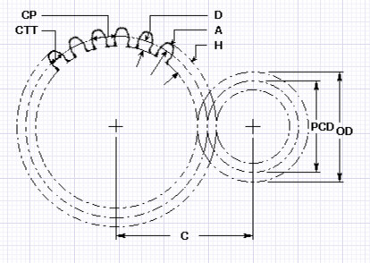
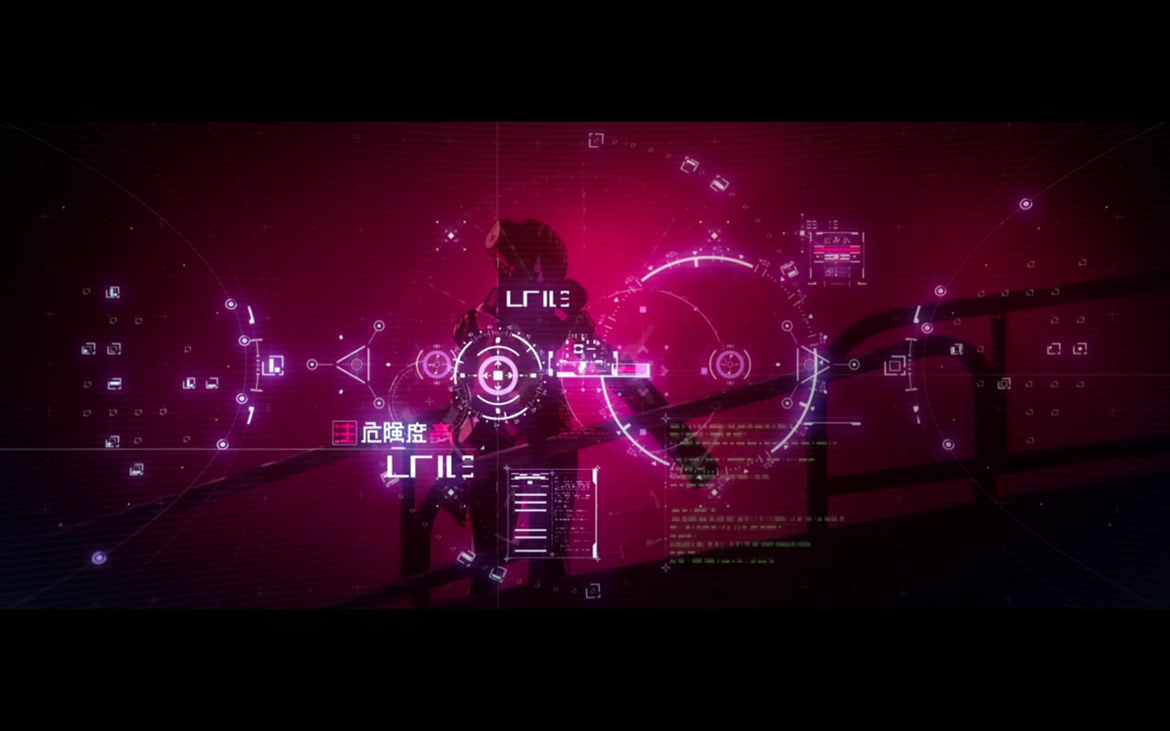
Still frame from the anime Blame!

or

Expanse 
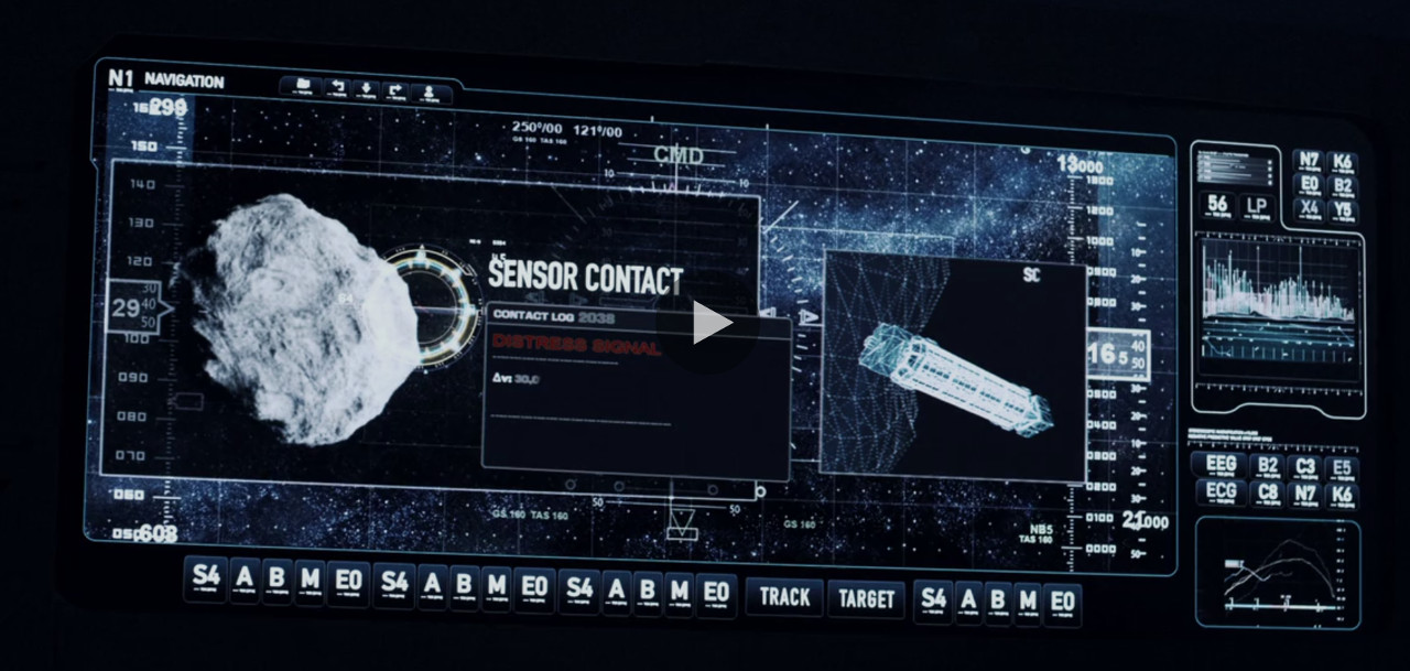
Still frame from the TV series The Expanse

We have a small collection of applications that are used for our rovers. Almost every autonomous challenge has client application (sometimes called 'the controller'). Like one we started writing for the Somewhere Over the Rainbow challenge:

camera-example-old

Or application for calibration of servos and ESCs for the wheels:

calibration-old

Or one of the latest addition - tiny application that reads local computer's joystick (or keyboard) and sends data to the drive service.

jcontroller-old

But, even though they are functional they didn't have the style or anything that cutting edge science feel in them. And, after all, we are dealing with some kind of progress. So, there came in our little distraction. So, after a weekend of technically useless and visually pleasing work we've spruced up our UI side of our apps. So, Something Over the Rainbow controller ended up looking like this:

camera-example

Calibration app:

selecting-rover

Joystick controller:

jcontroller

Since almost all of our apps follow very similar pattern it was very easy converting other old apps to use new UI style. Here is, for instance, app we created to test accelerometer:

accelerometer

And there are a few others as well... If competition is to be won by fancy graphics, I think we would be among the winners!

YOne Challenge Down - 6 More To Go


Last year our attempt at Slightly Deranged Golf with a 'kicker' didn't go the way we expected it. The best go was when we tucked the golf ball under the 'kicker':

last-year 
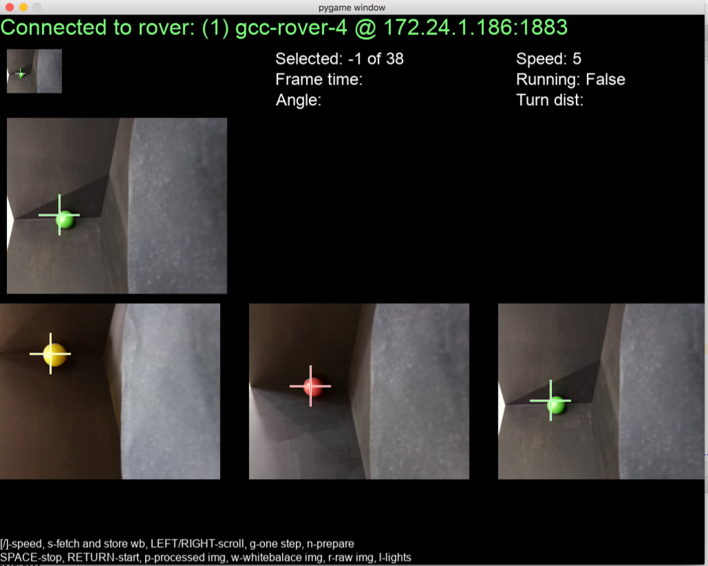
Also, it seemed that the best results others achieved were when they had some way of 'capturing' the ball.

The design idea for this year was simple:

design

The main part is a 'scoop' attached to the rover and one servo with a moving part that will serve at the same time as 'catcher' and 'kicker'. Back to 3D printing and after a few prototypes for our box of discarded parts, we had the final design (on the right on the picture below):

[gallery ids="1237,1236,1233" type="square"]

One of the previous prototypes had 90º angles at the front which, after analysing last year's challenge turned not to be the best idea.

half-finished

Slightly Deranged Golf had uphill slope at the end which might turn to be a challenge on its own if front part of our attachment is going to catch it. The final design now has nicely rounded edges which we hope will allow us to push ball up hill as well. Also, in last moment change we've added place for the distance sensor as well so we can detect when windmill blade passes by...

Here is the attachment for Slightly Deranged Golf on the rover:

finished-golf

With some coding in our joystick controller service we managed to put all quickly together and here it is in the action:

YDual VL53L0X Distance Sensor


Update: there is important update section at the end of the article!

One of the options we are exploring for our rover to find its position is with a distance sensor. Last time we went with single VL53L0X attached to a servo. The idea was that moving it around from -90º to 90º we could scan the rover's surroundings and make decisions. And it worked.

We were able to go through the maze relatively quickly, but observing other competitors we've noticed that those that had 2 or even better 3 distance sensors were able to move much quicker as their position relative to edges and end of the corridor were relayed at the same time. So, this time we decided to have two distance sensors. The original idea was to use ultrasonic sensors (HC SR04) and a breakout board with a ATmega328p connected to the RPi with i2c; More about it in one of the following blogs. In the mean time, until our i2c solution is finished, we've created plan B solution - two VL53L0X sensors on the same i2c bus. Here's the physical design of the holder Prototyping.

But adding two VL53L0X on the same i2c bus is not a simple thing. Unlike many i2c devices, VL53L0X doesn't have a selectable i2c address (usually jumps on the board). It uses separate pins for a logical 'enable' (or in this case 'disable'). Pin XSHUT needs to be set to logical '1' for the sensor to use i2c bus. Internally, it has a pull-up resistor so if not connected it will still work. Setting XSHUT to logical '0' (GND in our case) makes it disabled.

Since we only need two VL53L0X sensors it can be done by simple 'not' gate - where one sensor is directly connected to the spare GPIO of the RPi and another through the 'not' gate. Simple logical circuits are easy to find and use, but in this case would take slightly more space than needed as the same can be achieved by simple transistor!

Here is the schematic for our little adapter for two sensors:Not-Gate
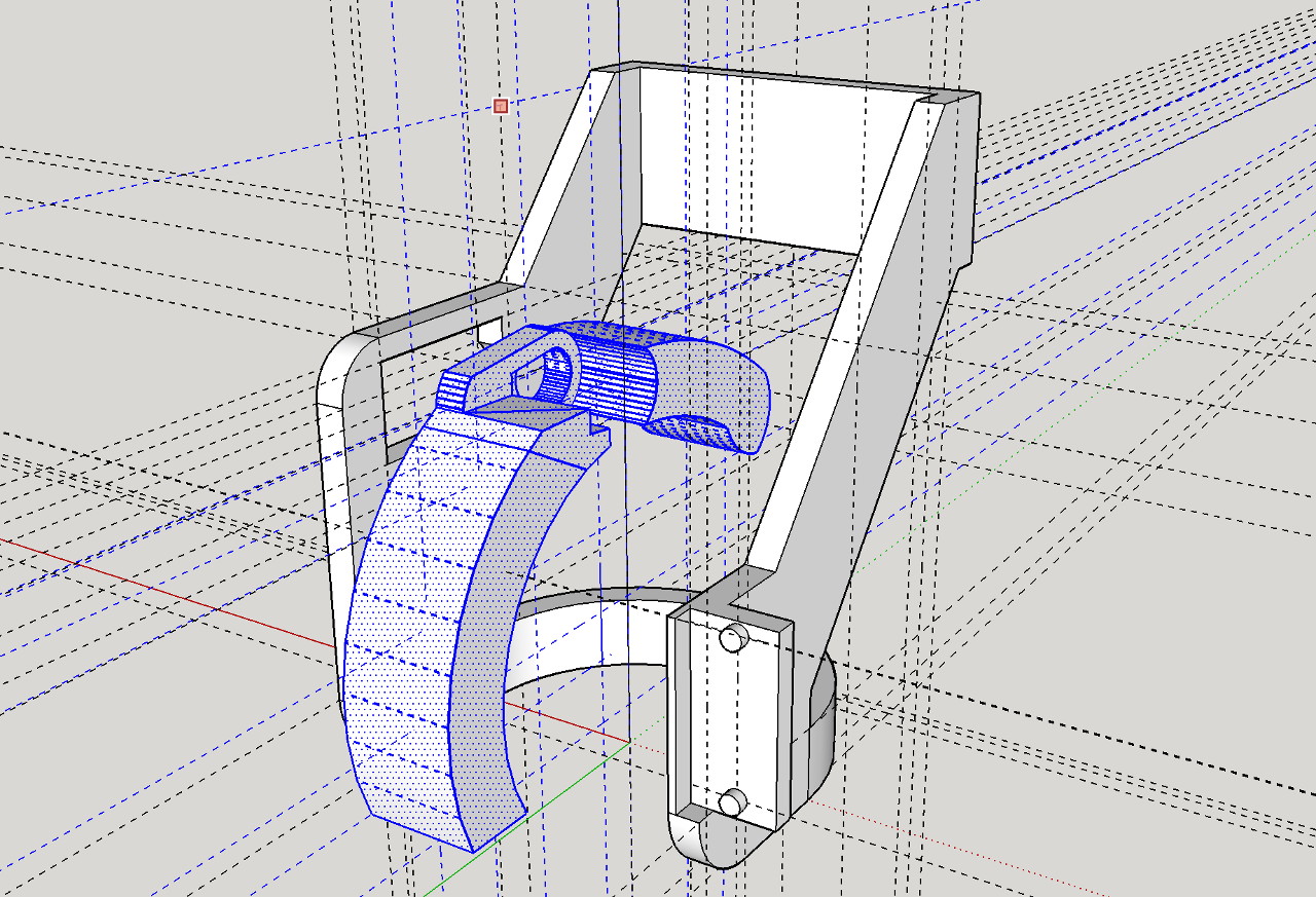
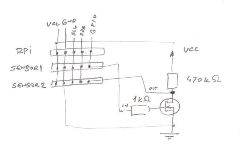
FET transistor 2n7000 (which, btw, I somehow had in box of spares) seemed to be ideal for the 'not' gate.

After sketching the circuit, it was just matter of putting all of it on the breadboard and testing it out. It would have been a 10 minute job if someone didn't forget that Servoblaster on a RPi does not release ports even if they are not actively driven. So, after half an hour of scratching heads and spare, not used, GPIO identified (GPIO 4, which, just to make things worse was set as a one wire interface!) things finally started working!

Not-Gate-Breadboard

After proof of concept it was quite straightforward - a tiny stripboard PCB with only three lines to break would yield a 15mm x 15mm x 10mm device:

Not-Gate-PCB

Which after soldering ended up looking like this:

Not-Gate-PCB-Done

And when is all put together like this:

Not-Gate-PCB-Done-Connected

So here is our GCC Rover M16 with two distance sensors as originally designed here 2018 Inaugural meeting:

[gallery ids="1180,1182,1181" type="rectangular"]

Now we need to only  write software to read both and provide values through our PyROS and a few small algorithms (like following wall to the corner or finding corner) to utilise those sensors.

Update: Never read half of a blog/document. The important stuff might be near the end!

The XSHUT pin resets the sensor and enabling it again it needs some time to reset. Fortunately that time is only 1.2ms but setting up the sensor (after boot) takes some time, too, and there is time for ranging (scanning) on top of it. In the above configuration there is now a way having both sensors ranging continuously at the same time. With a not gate software sequence that would:

  • reset and enable one sensor
  • set it up
  • read one off distance
  • repeat for second sensor
Many would agree that this is not the most optimal way of utilising the sensor. Plus we wouldn't expect fast readings of the distances.

A much better way is to connect one sensor's XSHUT directly to VCC and the other's to GPIO and utilise another function of the sensor: the ability to change i2c address of the fly! So, after updating the board for FET to keep the VCC on the output our algorithm is now:

  1. make sure GPIO is high
  2. check i2c device on address VL53L0X_REG_I2C_ADDRESS + 2 is present. If so go to step 5
  3. make sure GPIO is low so only one sensor is 'online'. Other is 'shut'...
  4. change address of device on VL53L0X_REG_I2C_ADDRESS address to VL53L0X_REG_I2C_ADDRESS + 2
  5. make sure GPIO is high so both sensors are 'online'.
  6. check if i2c device on address VL53L0X_REG_I2C_ADDRESS + 1 is present. If so finish.
  7. if not change address of device on VL53L0X_REG_I2C_ADDRESS address to VL53L0X_REG_I2C_ADDRESS + 1
That way both sensors would be moved to two new i2c addresses using only one GPIO to control only one sensor. Much simpler than having extra not gate, too.

[gallery ids="1231,1230" type="rectangular"]

And output after sensors were initialised:

two-sensors-working

YSomewhere Over The Rainbow


This is blog post about making the 'arena' for the Something Over The Rainbow challenge.

The Bill:

9mm MDF 2440mm x 1220mm board - £16.80

Corner Brace 40mm - £7.74

3.5 x 12mm screws - £2.88

Blackboard paint - £5.90 (£11.60 as second coat was needed for removing grey quarter circles)

Art Attach PVA glue - kids had grown up sufficiently not to notice half is missing

Total: £33.32 (£39.32 - with second coat of paint)

Start of the build: [gallery ids="1215,1216" type="rectangular"]

Ready for carrying it around:

testing-for-transport

Checking the size of the arena vs rover:

checking-scale

Sketching corners:

where-are-corners

First, live test...

live-test

... has successfully passed - with a hamster!

Priming equipment:

priming

Painting:

[gallery ids="1206,1205" type="rectangular"]

Putting it all together:

rover-in-arena-black

Question: Grey corners or not?

rover-in-arena-corners

First test of software coloured balls detection (happy path - almost no cheating):

yellow-red-green-spot-on

(don't get confused - camera is mounted at 90º CCW)

Update: Patience is a virtue... So mere couple of hours all was done:

rules-decision

So, here we go again - second coat of paint:

second-coat-of-paint

Grey quarter circles: now you see them - now you don't!

And - over the weekend we discovered that screws on the bottom of the arena have bad habit of damaging furniture (i.e. dinning tables). So, here are finishing touches to address it:

[gallery ids="1223,1222,1221" type="rectangular"]

Next step: coding!

YStatus Update


We were quite busy last few weeks. Our first priority was to make sure all rovers are operational. Motor swaps, new wheels, and other minor repairs where needed since last PiWars. And now - all three are updated to the latest spec and even upgraded. Last rover got MPU9250 9 axis gyro/accelerometer/compass breakout board and all got extra pin provided at our 'i2c' bus. Now not only we have GND, VCC (3.3V), SDA and SCL on the cable for attachments, but extra GPIO - GPIO 4 which, in theory, can dub as One Wire Interface, too. Currently that pins purpose is to select between two VL53L0X sensors.

ThreeRovers1 Aside of making rovers up and running, we, as you have seen in previous blogs, have undergone another major change - switched from WiFi/TCP/MTQQ communication with the rover to Bluetooth directly to the rover. Now two rovers can be controlled remotely (previously we would be using a computer with wired game controller) - one with old style MQTT communication and another with PS3 game controller. That allowed us to start practising where we lost in final of one of the challenges: PiNoon.

PiNoon-3

We undertook that task quite seriously:

Aside of having fun bursting each other balloons we had quite a serious task designing new (and secret) controls and special moves:

ClubActivity2

Also we did quite a lot on 'behind the scenes' software regarding controllers. See here https://gccpiwars.wordpress.com/2018/02/10/our-controllers-and-why-indentation-is-important/.

ClubActivity1

In parallel to it, we are exploring ability to use ultrasonic sensors HC SR04HC SR04 as they are much faster to measure distances than VL53L0X and theoretically equally precise. Our original idea was that Raspberry Pi would be sufficient to trigger the sensor and measure time of response, but with multi-tasking non real-time operating system it turned out to be quite messy operation.

ClubActivity3

Because of that we started working on Arduino/ATmega328p solution where it should act as slave i2c device which will use 16-bit timer (Timer1) to measure time from trigger signal to echo. Current status update is that using Arduino Wire library for i2c and sensor library for reading ultrasonic sensor doesn't work quite well due to interrupt clashing, but some of the following blog posts are going to explore it in depth and, hopefully, announce solution.

gun-1

Aside of that, we have started working on nerf gun (ground up solution) and recognising coloured balls for the Somewhere Over The Rainbow challenge.

RedGreenBlueYellow

More updates next time...

YPrototyping


It is time for prototyping again! For our first PiWars we adopted iterative approach: design, mock, test, improve and repeat. That lead to lots of iterations and lots of discarded parts.PrinterParts

But was that necessarily a bad thing? So far it seems that at least half of the 'previous versions' have found a kind of home - for people who wanted to try putting together a rover of ours and are not worried having the latest, the most refined version of it. Also, it helped us to find out what the 'dead ends' and the 'wrong decisions' were like and we learned from them. Beside that, it made our club members not be scared of trying out stuff even if it originally seems not to be the best idea that we can come up with at that moment.PiNoonHolderWithDistanceSensor

Now we are at quite a few new designs. One of the first we did was PiNoon capture nut (ahm, electric connector) and with distance sensor (VL53L0X). One of the previous blogs was about capturing stuff in 3D printer objects.

CalibrationWheelCalibrationWheelPrinted
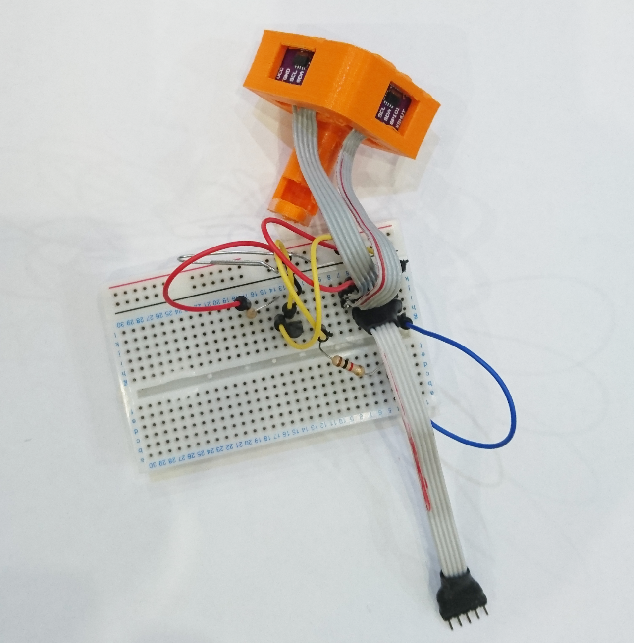
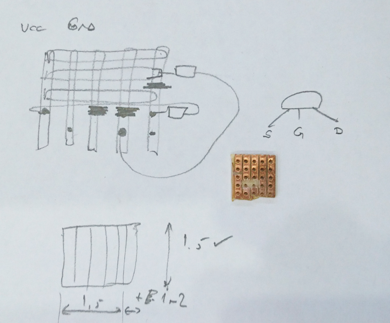
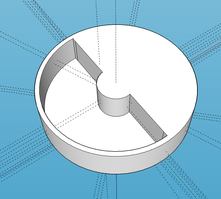
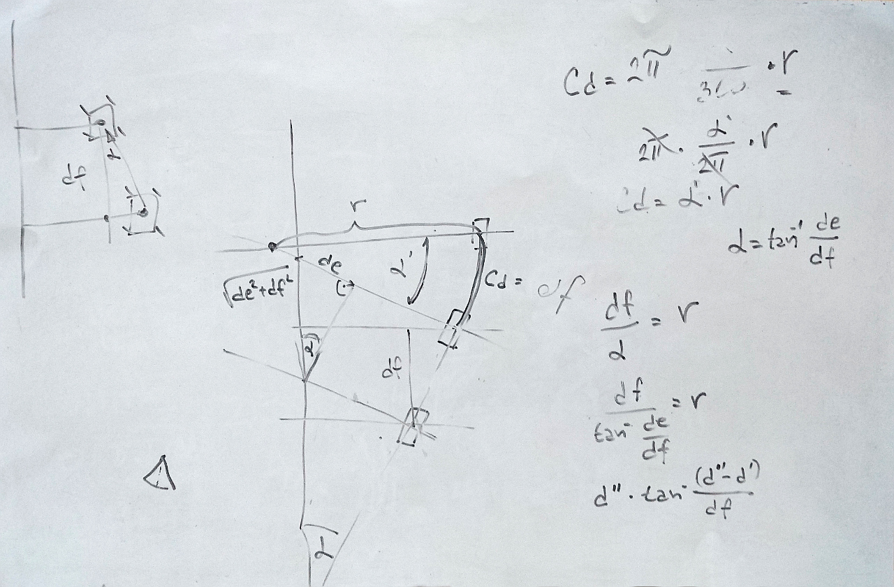
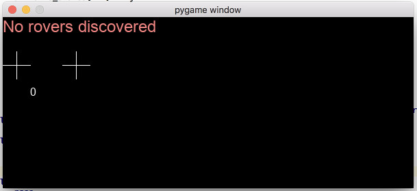
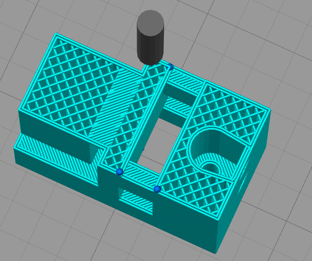
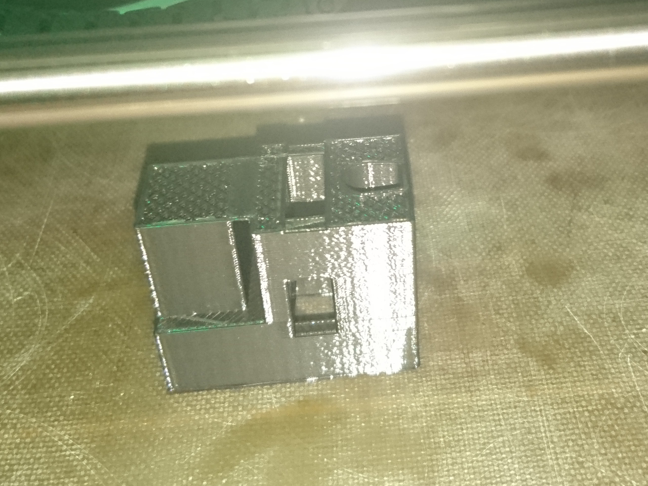
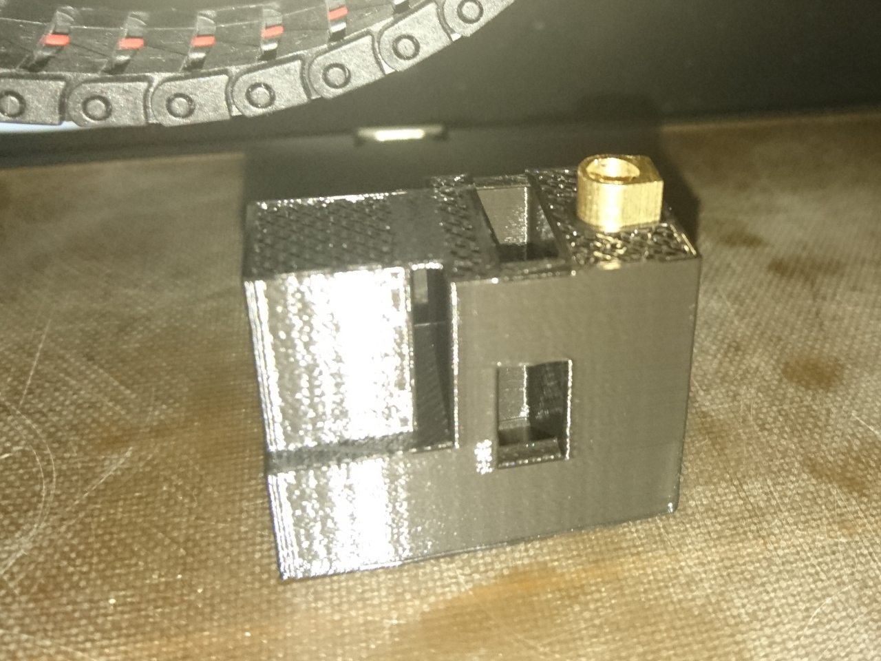
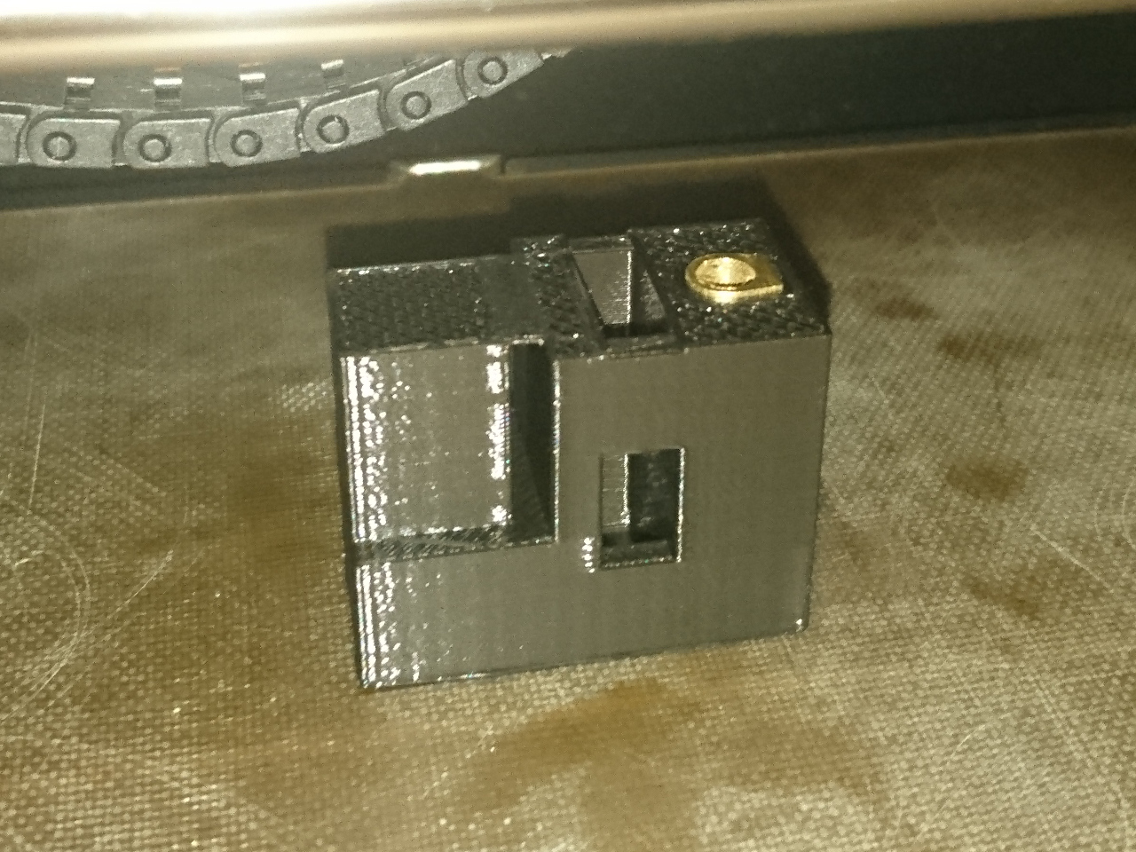
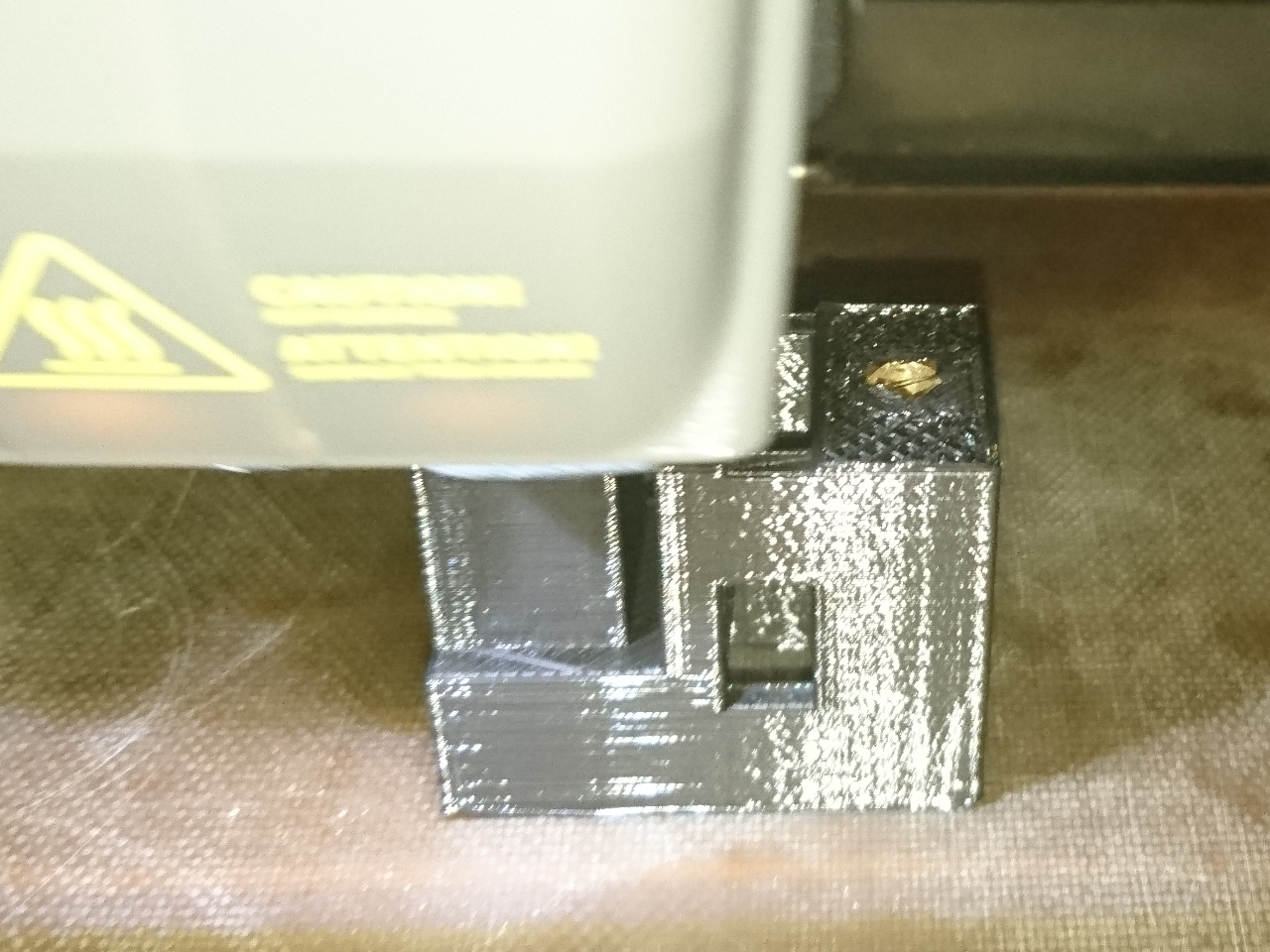
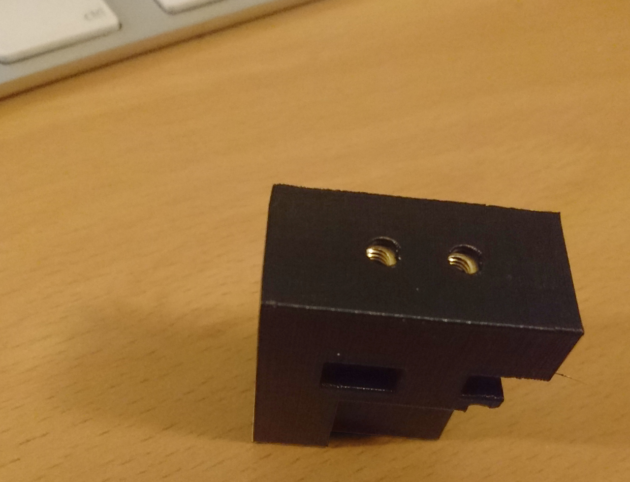
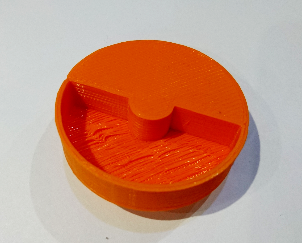
Next was a wheel to help us calibrate the (non load) speed of the motors. It is half filled in and half 10mm indented - an attempt to use same distance sensor for calibrating speed of the wheel. The idea is to put the sensor at some close range (10-20mm) and spin the wheel, counting how many times a second it measured the shorter distance to longer distance. Its target speed can be 120RPM, which is 2 times a second - and the default VL53L0X 'time allowance' is 33ms, we should be able to do 30 samples of which 15 should be shorter distance and 15 longer. The software for it is still pending.

Two Distance Sensors Holder

The last design is our work towards The Minimal Maze and Somewhere Over The Rainbow. The two VL53L0X sensors at 90º attached to our standard front, downward facing servo will be quite a complex 3D design.

[gallery ids="1176,1175,1173" type="rectangular"]

Originally it was designed as two parts but as 3D printers can print things with support material - this was the perfect candidate for it. So, here is the redesigned model:

[gallery ids="1177,1172,1171" type="rectangular"]

One of the following blogs will cover the connecting of two VL53L0X sensors using a FET transistor as a NOT gate...

Aside of those there are still outstanding for capturing the golf ball for Slightly Deranged Golf and The Duck Shoot that are still to be built. More about it later.

YOur Controllers (and why indentation is important)


To control our rover we have our standard controllers. Last year we used a modified ps2 controller with a PiZeroW inside. This enabled us to remotely send packets through the WiFi. This was a relatively easy way of remotely driving the rover. However, it had some flaws. Firstly, because it used the WiFi hotspot that we had to carry around, it meant that the TCP packets would have to first be sent to the hotspot over WiFi, then to the rover over WiFi, and data was sent back through the same path. With lots of other 2.4GHz traffic on the spot at times we had latency of up to second or two!

PiWarsControllerSetupOld

So, this year we are planning to cut the corner, and connect a controller directly to the rover.

PiWarsControllerSetupNew 
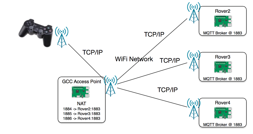
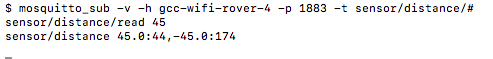
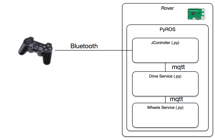
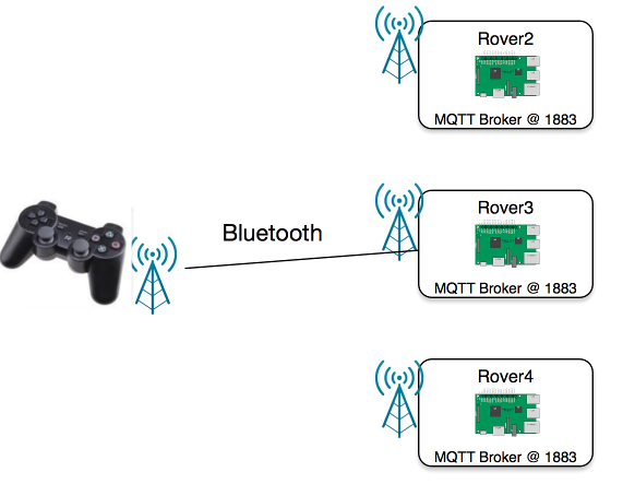
The way we will do this is with a (knockoff) PS3 controller, connected via Bluetooth to the rover. This is way better because there would be far less points in the packets route, and because its more direct, it should have a shorter travel time, meaning less delay. Also, there is no three way acknowledgement TCP robustness relies on. YAY!

PiWarsControllerSetupOldSoftware

So we set to work on coding this. First we had to connect controller to (the pair to) the Raspberry Pi. Then we, needed to make some code to actually utilise the controller connected in /dev/input/js0; the place that any Bluetooth/USB/Wired controller would connect to. Because on the modified PS2 controller with a PiZeroW we connected the controller inputs on the RPi in a similar way, to still appear as a controller on /dev/input/js0, we could easily just transfer the code. All that was needed was to knock off a few lines to disable the s1306 screen, because they were not needed, and just patch up the code to work with this controller.

PiWarsControllerSetupNewSoftware

All was working, but we noticed a problem. All the inputs were really delayed, with the delay increasing by the minute. Something wasn't right.

Silly Problem

Then we realised the problem. Because we still used PyROS to send packets internally in the rover (which was instantaneous) we needed to loop the controller service's thread, to process keys, buttons and sticks. This meant that we were sending packets at around 50 times a second, so we thought. However there was a little problem in PyROS's code. PyROS would wait a set amount of time before executing the next step, and it would achieve keeping this timing with a loop, waiting for the right time to strike. In the code below you can see our mistake. While PyROS was waiting for the next time to run the code's processes (to read the inputs) it would constantly read them anyway. This meant that we were sending packets at around 5000 times a second.
def loop(deltaTime, inner=None):
    for it in range(0, int(deltaTime / 0.002)):
        time.sleep(0.0015)
        if client is None:
            time.sleep(0.0005)
        else:
            client.loop(0.0005)

    if inner is not None:
        inner()

Because of it 'inner' code was executed with total delay of 2ms instead of originally expected 20ms and thus spamming drive with messages (or just stop). The drive service managed to process 10 times the volume of messages, but was giving four to eight times that much messages for the wheels service (one or two message per wheel - one for position and one for speed) which at peaks produced 400 extra messages per second. This meant that the wheels service would clog up with messages to execute, and not be able to execute them in the queue in time, until it has process the other hundreds of useless messages. A bit of a silly mistake there!

YRumbling About LiPo batteries


This is originally written as a 'manual' for our club members that are borrowing rovers. As our rovers operate on LiPo batteries and they need special care, here is what one should know about how to handle LiPo batteries safely. Here are batteries we use with our rovers:

rover-batteries

LiPo Batteries

Our rover uses batteries that are two cell (nominally 7.4V) Lithium Polymer batteries. They provide quite a strong current and thus they are very dangerous if shorted. A short would generate high heat and can even cause the battery to explode. all-batteries

Charging

Batteries are charged using the ‘LiPo Balanced’ option on the charger. The voltage is 7.4V (two cells) and the current needs to be set between 1A and 2A. The batteries we have shouldn’t be charged with stronger current than 2A as it can damage them. Our batteries are 2100mAh with a ‘C’ rating that is calculated by dividing that number by 1000 (2.1A in our case). Normally batteries are charged at around 1 C and the batteries we have can provide up to 25C as per manufacturer’s description. When that is multiplied with 2.1A it comes up to them being capable of providing to ~50A of continual current. Fortunately our rovers do not ‘consume’ more than 1A up to 2 or 3A at peaks. That allows our batteries to last much longer between charges.

Charging batteries means making each LiPo battery cell charged up to 4.2V (8.4V together) and balanced means that they are charged in such way that each cell is separately ensured not to go over that voltage. That is achieved by connecting the battery with, not only the orange ‘beefier’ connector, but the smaller white to the charger as well. Balanced charging won’t start if battery is connected wrong way round (as that would be horrible fire risk) and the balance lead connected to the side of charger as well. Make sure that you connect balanced lead first and then, only then connect main connector – just in case, by accident, you force balancing to lean the wrong way in. This shouldn’t happen (nobody should be able to do it), but just as a precaution.

The normal charging cycle should last between 20 minutes up to an hour (if the battery is depleted and/or cells are badly out of balance). It is not a problem if it finishes sooner. During charge you can press inc/dec buttons on the charger and see each cell’s voltage. Batteries with LiPo chemistry should not be discharged more than 80% and as good practice we don’t really go below 60%. Percentage is calculated upon the finished charge where the number mAh displayed is divided by battery’s nominal capacity (in our case 2100mAh), so, in our case we shouldn’t be, really, returning more than 1200-1400mAh back to the battery. In case the battery ‘accepted’ around 1800mAh it is still acceptable and battery shouldn’t have been harmed a lot, but everything over that is directly shortening battery’s life. Another rule of thumb is that individual cell’s voltage shouldn’t really go below 3.7V. Literature is talking about 3.3V and 3.0V but if the battery is stressed that much it usually means that it is already harmed. Also, good batteries, when discharged for around 80% of their capacity will hold (resting) voltage levels around 3.7V anyway. When the battery's voltage is below 3.7V without load, it usually means that the battery is used for more than its nominate capacity or is already severely damaged through over-discharging, pulling current much greater over the manufacturer's specs of battery has lost its capacity through age.

charger

The Charger

The charger is operated using inc/dec buttons, the start button and for starting charging pressing start (which is at the same time ‘enter’) button slightly longer until battery emits sound then one more time to initiate charging. Pressing stop (The red button, on the opposite end to the start button) stops charging but it is only needed to be pressed in case you want to abandon charging. Normally when the battery is fully charged charger will make a sound and display a message on the screen. Do not leave battery connected to charger after it has been charged. Or, even worse when when charger is switched off. Batteries can be discharged by some leaking current and over-discharging this battery will definitively ruin it! The same goes for the rover: Never leave a battery connected to the rover as it will definitively spoil the battery completely.

What Then?

LiPo batteries have very good charge retention and can be left without being charged for long periods of time (years?!). The downside is that those batteries do not ‘like’ being left fully charged for long periods of time (that can harm them as well) so – cell voltage between 3.8V and 4V is ideal for storage.

How Long?

Empirically we’ve came to conclusion that our rover, no matter what is being done and how hard it has been made to whiz around, can operate safely with one LiPo battery for at least 1 hour. Probably two. Using it for over two hours would lead it to over discharge.

LiPo Bag

The LiPo bag is an safety 'device' - something that should be used each time batteries are charged. It is fire proof, fibreglass fabric bag which in unlikely case of something going wrong with the LiPo battery being charged will contain fire. (hopefully this never happens!)

lipo-bag

Last Note

I was told to make this post slightly less scary. So here it is:

If you are to use the batteries according to the manufacturer's recommendation and you never short it, puncture it, drop them (or hit it with a stick), overcharge it, overheat it or do anything mentioned here - all will be fine! smiley See - there's even a smiley!

YGCC Rover Open Source


Our rover software and hardware is now properly open source.

All the design changes will be posted here: https://www.thingiverse.com/thing:2763746

All the software is continuously updated here: https://github.com/GamesCreatorsClub/GCC-Rover

Also, current Android controller app is here: https://play.google.com/store/apps/details?id=org.ah.gcc.rover

And as all posts are not really worth without pictures - here is one:

pinoon
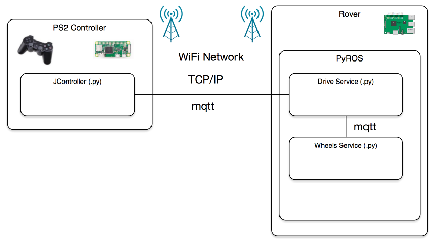
Guess what we will be doing on our next club meeting on Wednesday! :)

YGCC-Rover-M16


Here are full specs of our GCC Rover M16:

Type A / Type B

Dimensions Width Base: 110mm Max (wheels protruding): 125mm
Length Base: 160mm Max (with attachments): 225mm
Height Max: 120mm Clearance at bottom with 50mm wheels: 43mm
Weight Net: 490g With battery and an attachment: 660g
Wheels Diameter Base: 30mm Tyre (min): 32mm Tyre (max): 50mm
Width Base: 8.4mm Tyre: 14mm
Steering 4 wheels independently -90º to 90º
Power Battery 2 cell 7.4V Li-Po battery Charged 8.4V Capacity 2100-2200mAh
Motors DC mini metal geared motor 150/300 RPM at 6V
Speed Max (150RPM/50mm tyre) ~ 0.5 m/s
Max (300RPM/50mm tyre) ~ 1 m/s
Sensors Distance Rover type A: HC SR04 ultra sonic sensor Rover type B: VL53L0X IR laser distance sensor
9dof Sensor Rover type A: GY801 (gyro l3g4200d, accelerometer adxl345) Rover type B: MPU9250
Camera Pi Camera Module v2 (8 mega pixel
Controller Main Raspberry Pi 3

YIn The Meantime


Before we go elbow deep in mechanical design, electronics and programming - our existing rovers needed some sprucing up. All needed to be brought to the same specs and some previous design decision revisited.

servo-arm0
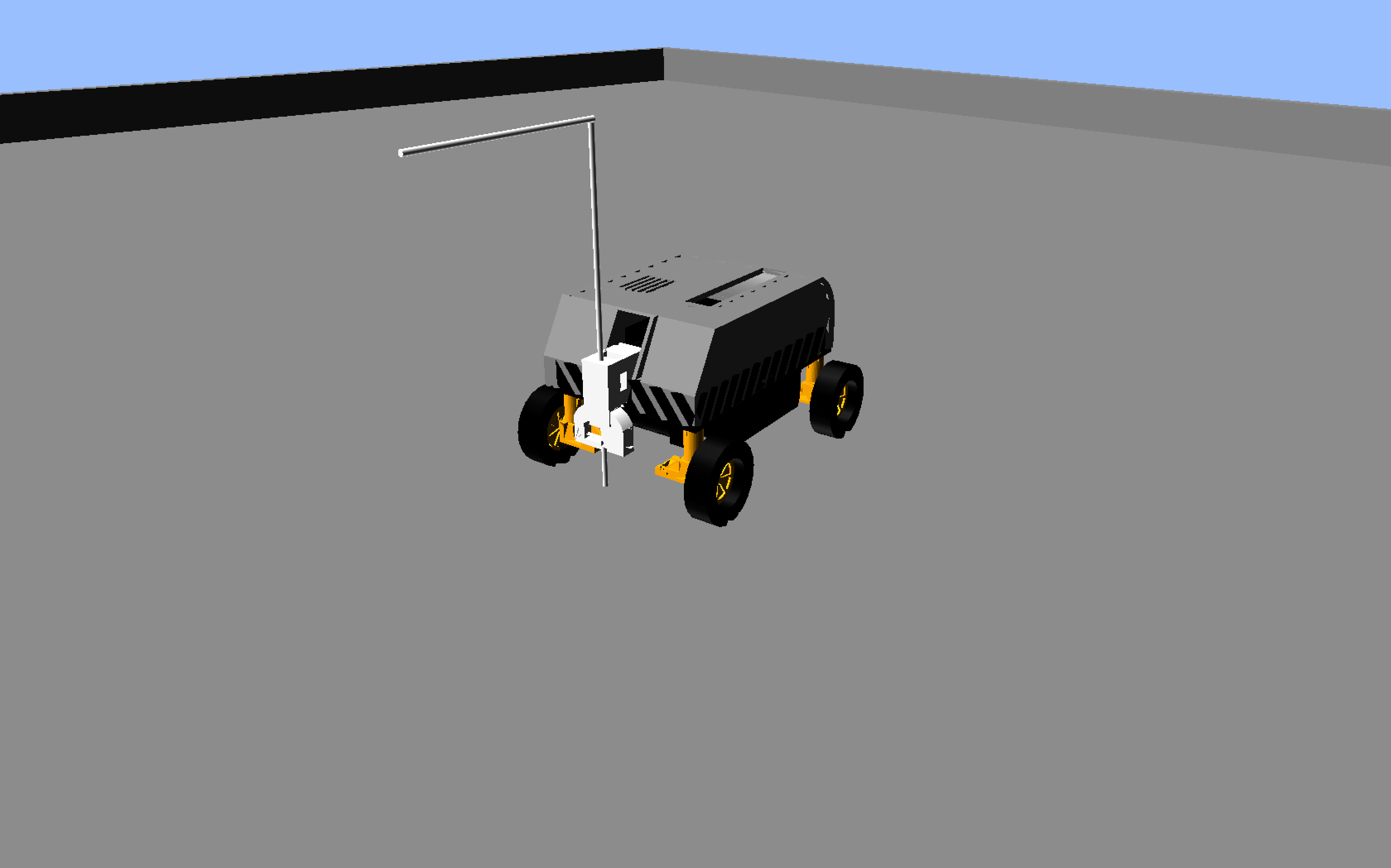
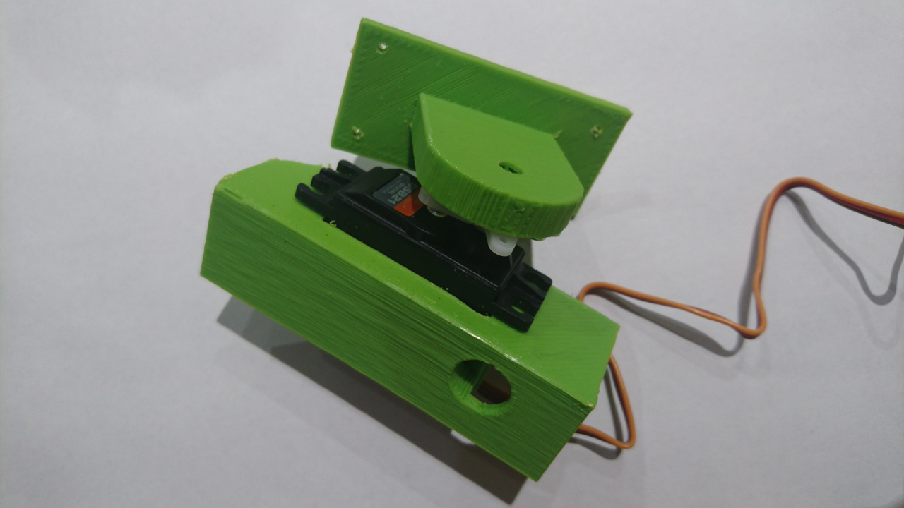
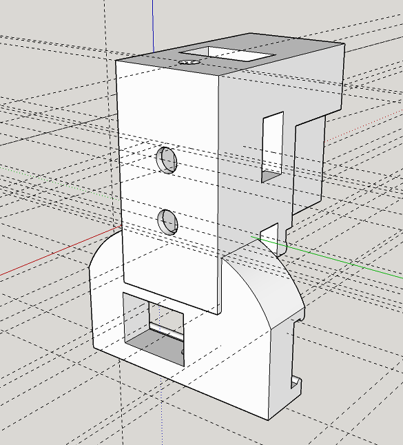
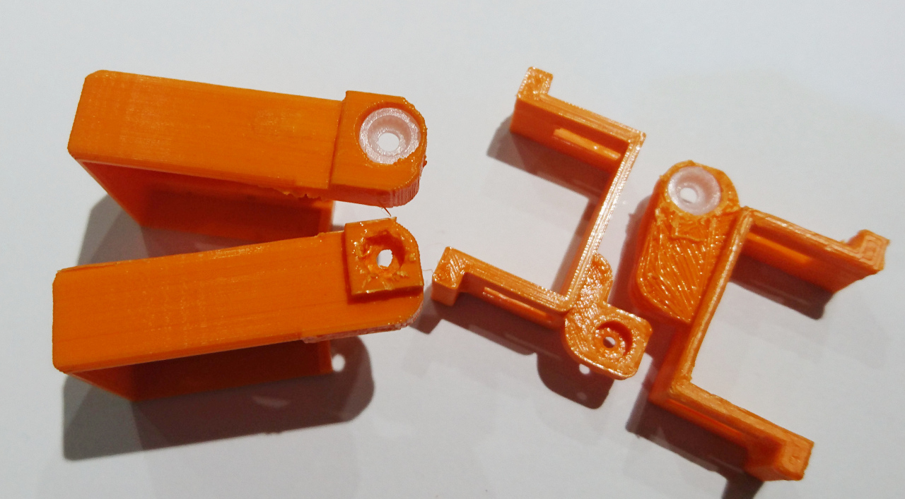
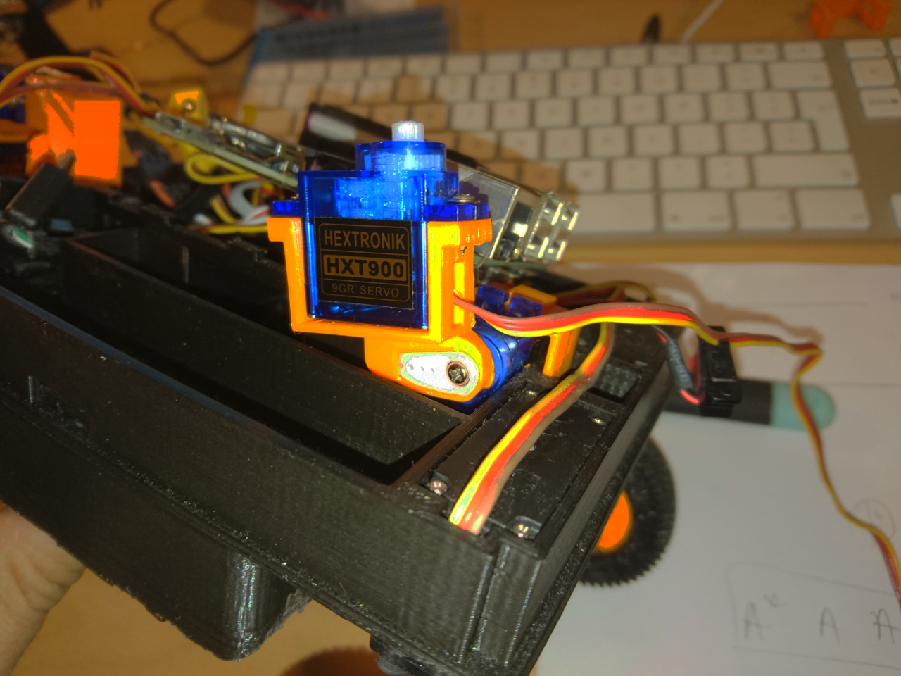
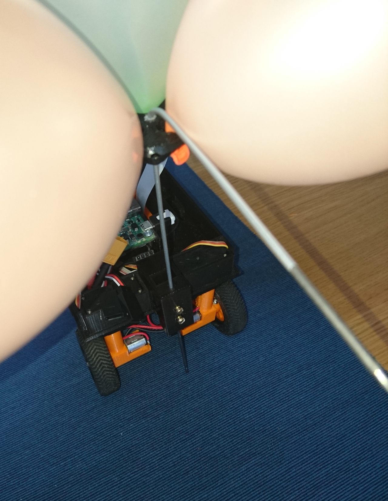
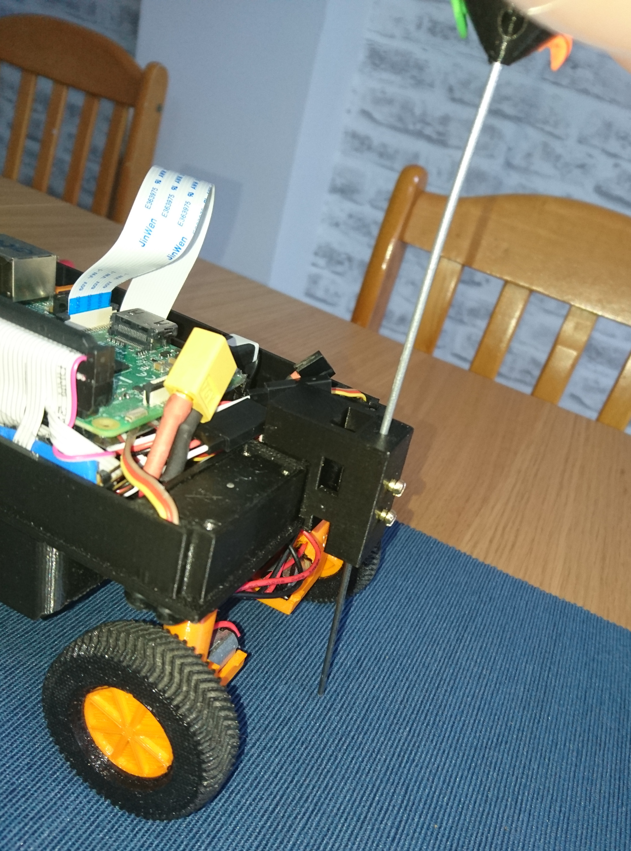
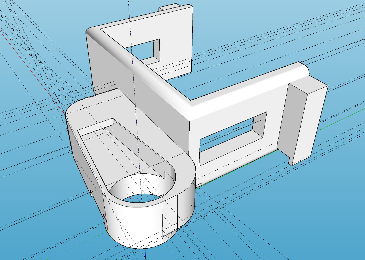
One of such a design decision was the way camera arm is attached to the servos. Idea was that if appropriate retched hole is made, servo shaft would fit and hold. It did to the extend but whole connection was a bit flimsy and would easily slip. Calibrating camera servos and then having the arm slip on the servo shaft would cause even more damage (or add to slipping, rounding the hole even more). The solution for this is to incorporate the original servo arms to the 3D printer parts. The result is here:

servo-arms-1.1   servo-arms-1

servo-arms-2 
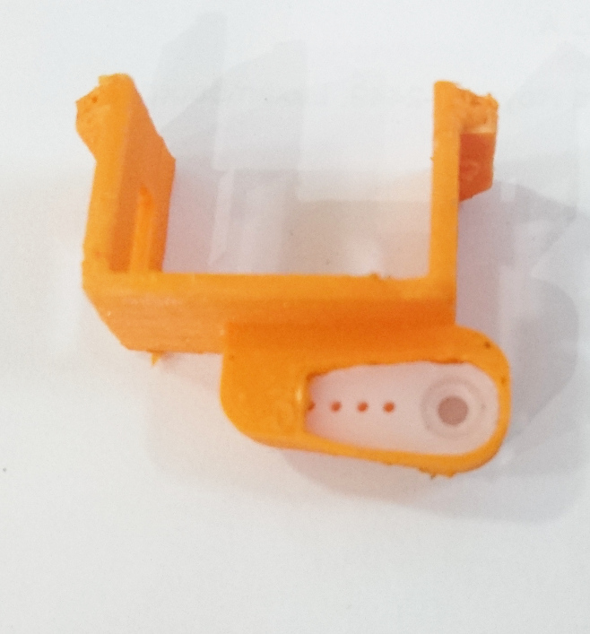
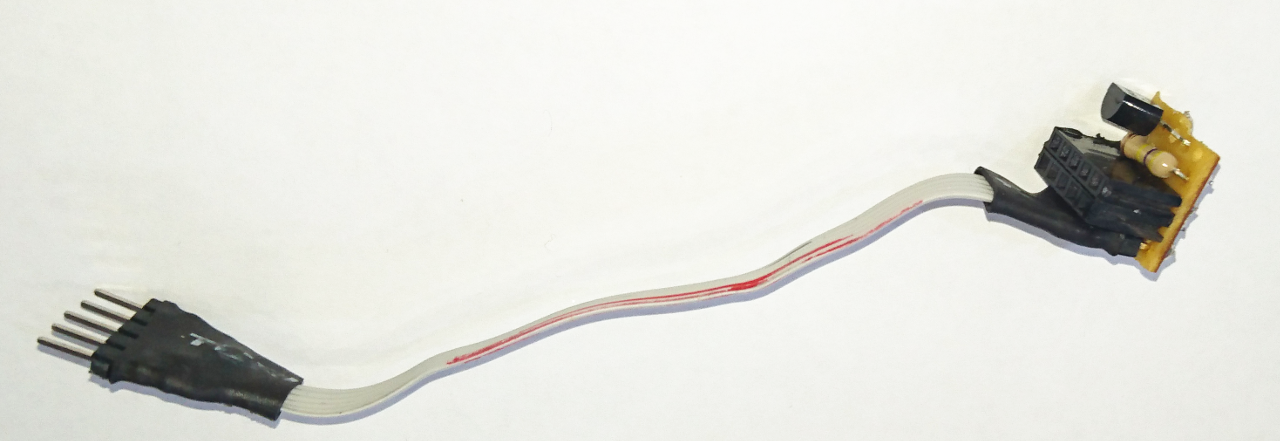
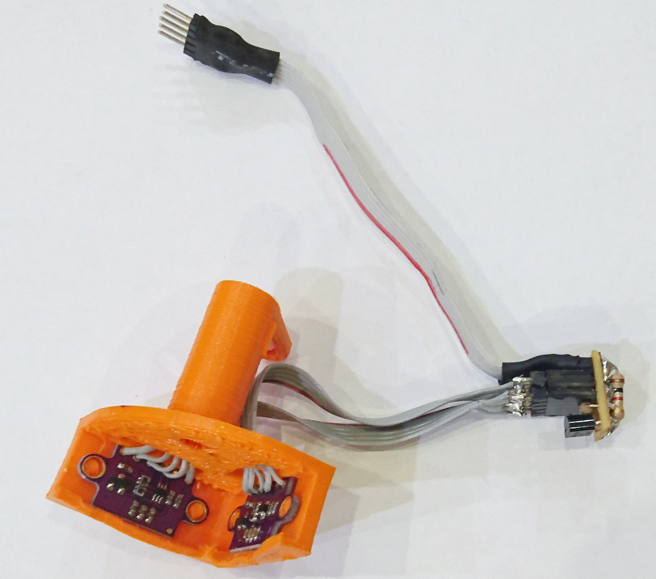
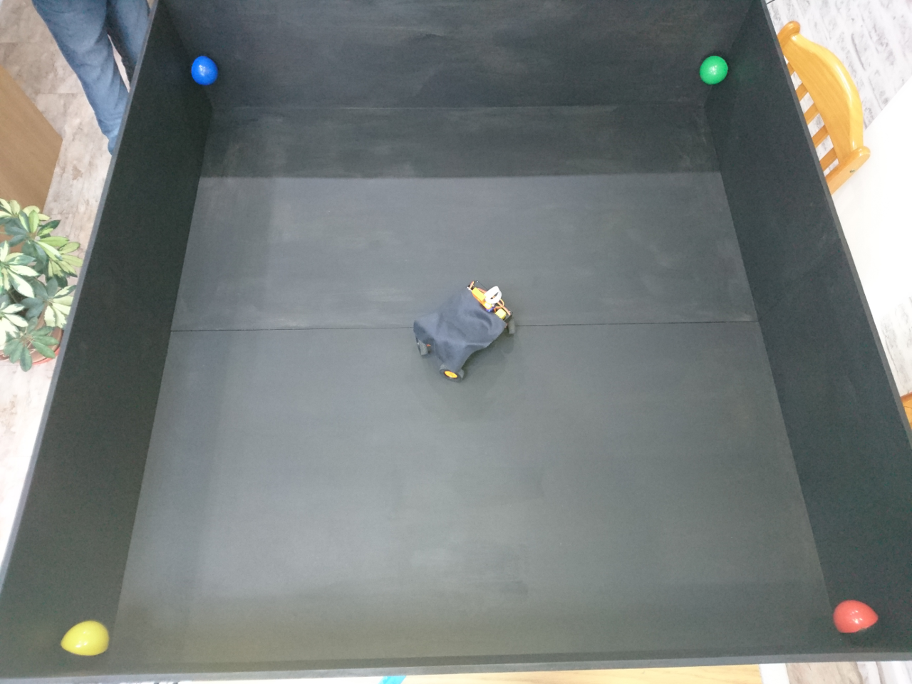
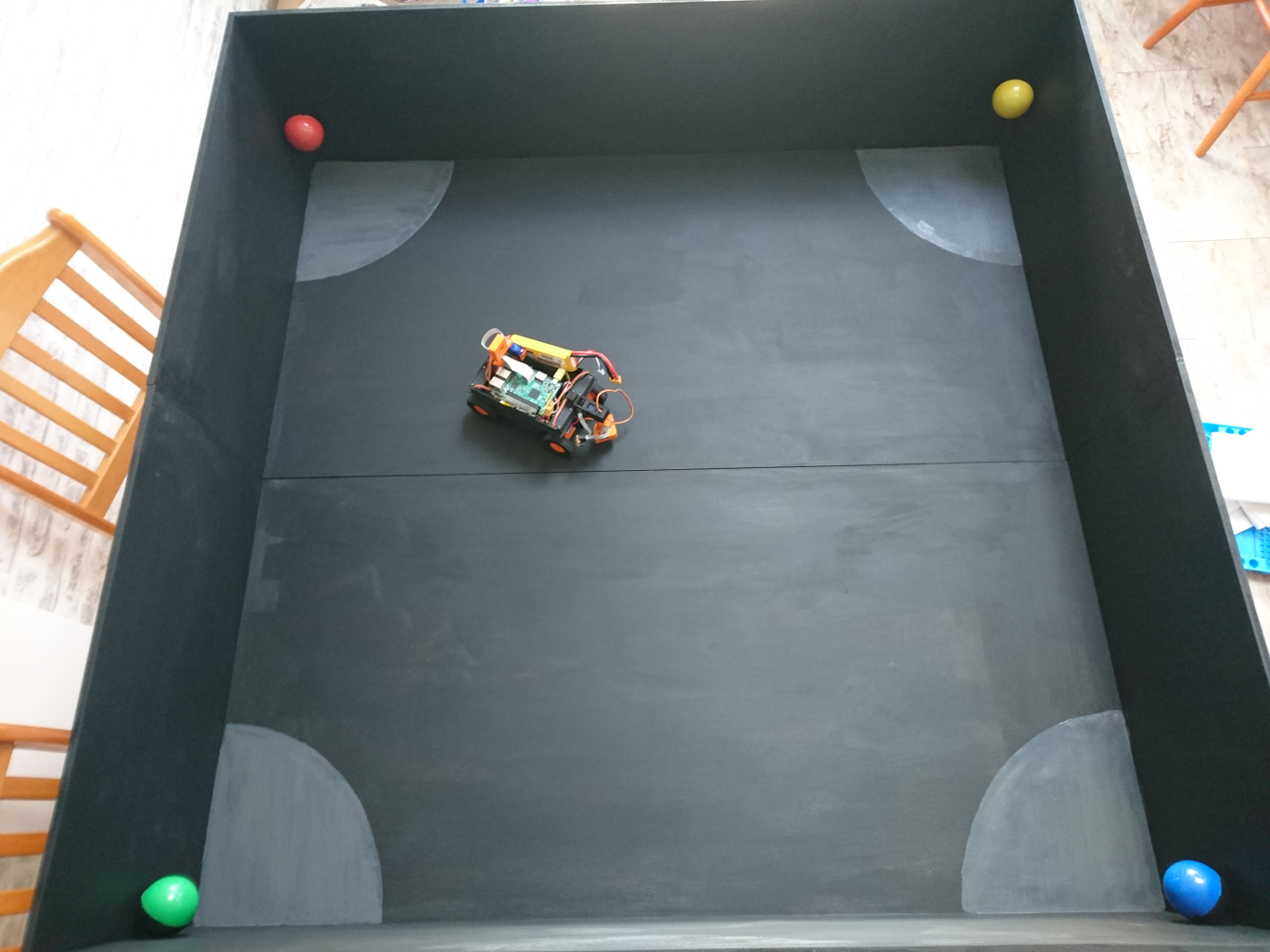
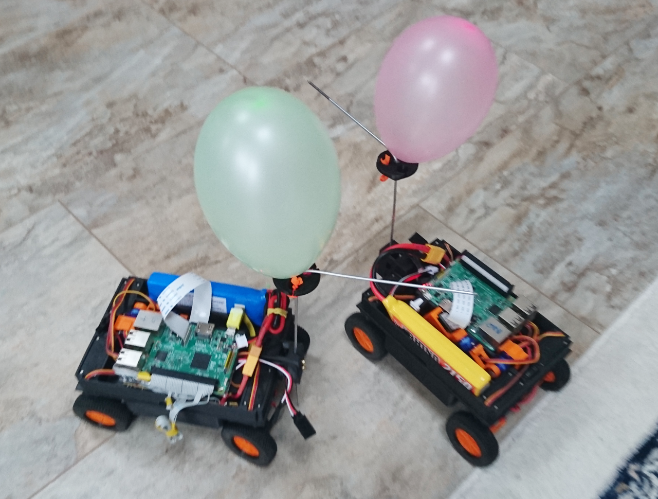
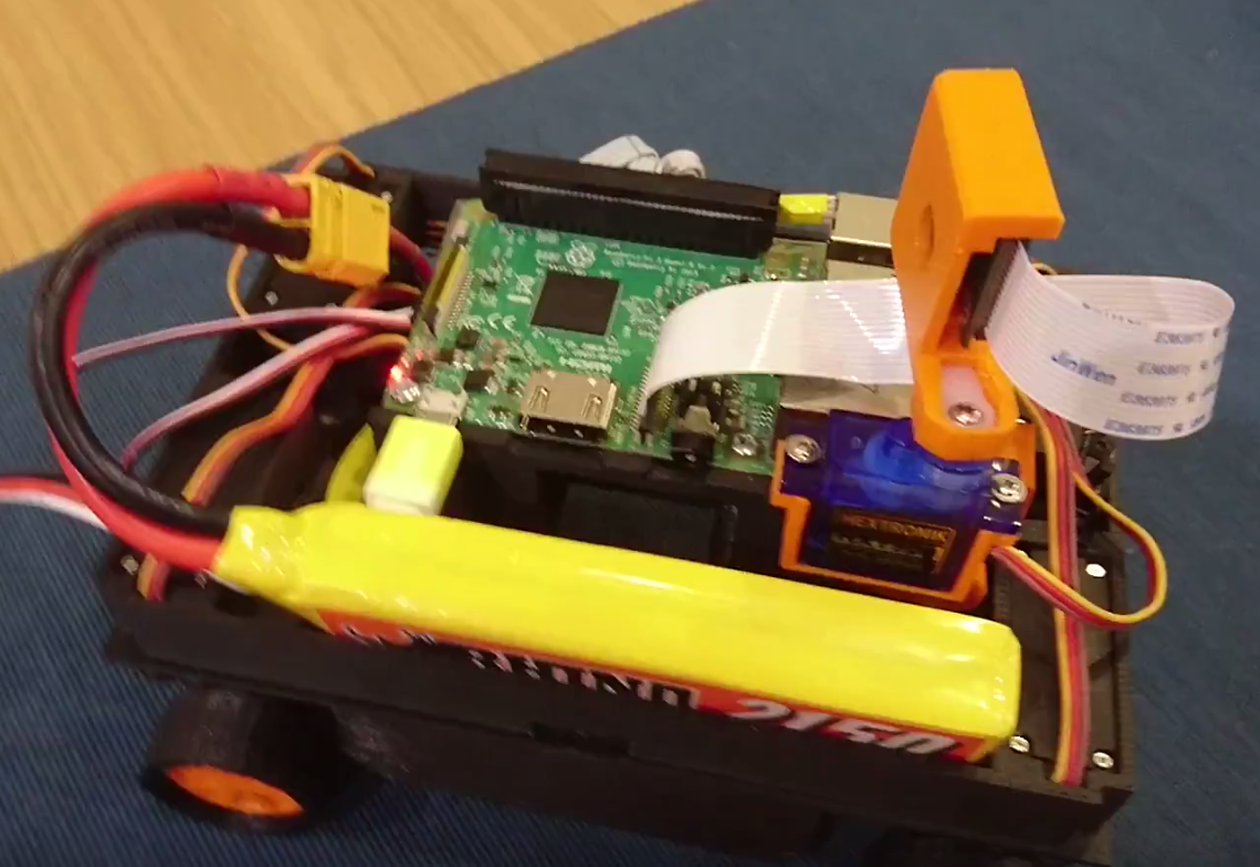
Now we have finally our 'secret' weapon ready to be deployed:

PiNoon

cn5

During 2017 competition we had advantage over most of the competitors because of the way the rod with balloons and pin was mounted. It wasn't the simplest solution - it had dual material (ninja flex and pla) 3D prints and plenty of tiny screws. We think it was the second best solution - the best one was the simplest - the humble electric connector.

cn2

So, in the mean time we returned back to the CAD and incorporated it in our design. Printing was less the trivial as it needed process similar to 'captured nut' where 3D printer needed to stop at particular point for above connector to be inserted:

cn-a1cn-a2cn-a3cn-a5

And here are the results:

cn1cn3cn4

Y2018 Inaugural meeting


This time we are starting very late due to many independent factors, but our resolve never faltered. Fortunately we finished quite strong last year - with two fully working rovers. However one lagged because it was built first and not upgraded completely. We only had very little damage, mainly on some attachments (broken servos mostly) and some of these we aren't going to need this year.

The only area, though, was that we didn't do as much as possible with software! Who would tell - given we're really a software club. Eh. Anyway, on our first meeting we went through all challenges and seeing what we had, and what we'll need to do to successfully complete them:

  • Straight-Line Speed Test - we need new a distance sensor configuration and new software
  • The Minimal Maze - even though we can go with our existing software, improvement in distance sensors and some new software could make it far faster
  • Somewhere Over the Rainbow - hardware wise we have all we need (even though new distance sensors again could improve overall performance), but the software will be a challenge
  • Slightly Deranged Golf - we need some new ways of capturing the golf ball
  • Pi Noon - we have all we need but can improve on the way the pin is held and we could add some more 'secret weapons and moves'; we also may need much more training
  • The Obstacle Course - we need different way of communication between the transmitter and the rover
  • The Duck Shoot - that's the hardest challenge given that we have little time to devise shooting mechanism

Straight-Line Speed Test and The Minimal Maze

Previously we had one sensor attached to a servos which allowed 180º of freedom but for quick maze run two seem as a minimum, while the Straight-Line test would benefit of two as well as Somewhere Over the Rainbow. So, next is to design a way of attaching two distance sensors (to start with, a simple HC-SR04) and make them read accurately. Our first attempt last year was to use a Raspberry Pi to read the distance, and hardware (voltage divider) was built in PCB of the rovers. It wasn't accurate enough as the Raspberry Pi was doing so many things at the same time and the results were all over the place. We tried to replace them with specialised a infra-red i2c sensor, but its internals were poorly documented and the sensor itself wasn't cheap.

sensors1

Now we are planning on going with an Arduino (ATmega328p) that will act as a i2c slave and allow control of two HC-SR04 sensors at the same time along with driving one servo that will move sensors around. That will allow these three configurations:

sensors2

Somewhere Over the Rainbow

For Somewhere Over the Rainbow we need to finally get our secret weapon out: the camera!Screen Shot 2018-01-16 at 20.44.37.png
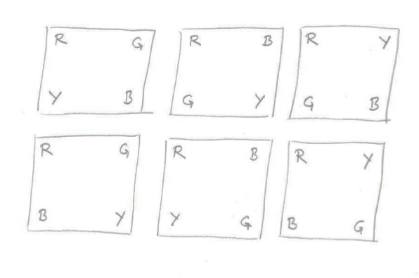
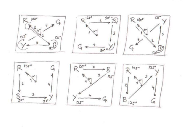
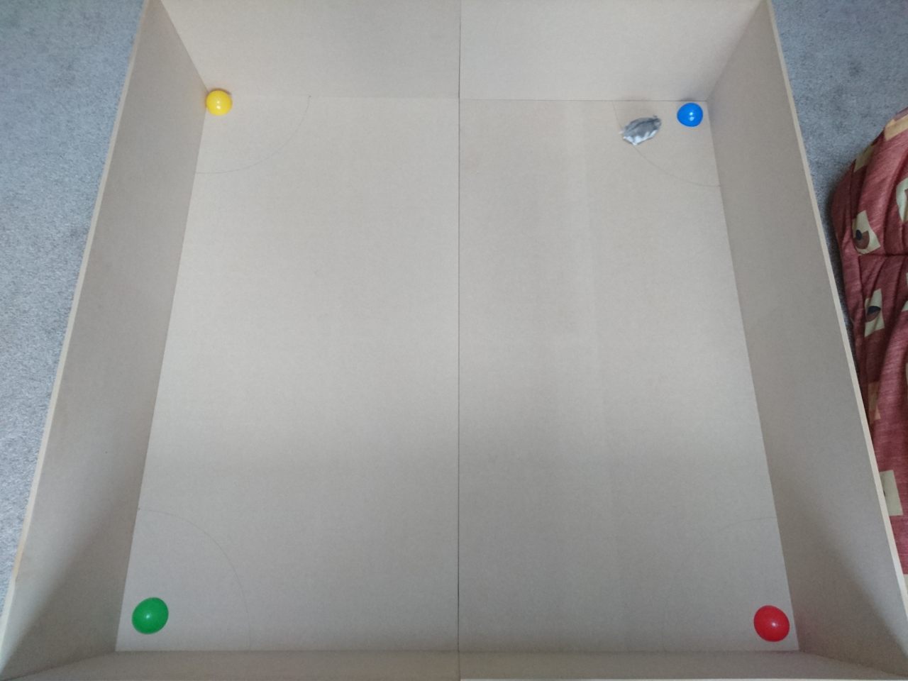
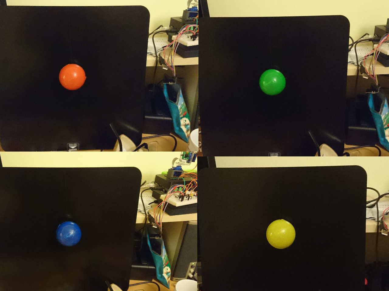
It was supposed to be used for follow the line (never worked as planned). Our first go will be in adopting existing software which captures images from the camera and scales them to 80x64 pixels and moves them to numpy for processing. The idea is to use as simple code as possible for detecting the presence and position of red, blue, yellow and green on the picture. Also, the code should be as modular as possible so we can, given enough time,  later switch to use more advanced software like OpenCV.

Slightly Deranged Golf

Last time we were lucky - in the second go we realised that kicking the ball is not as good as holding it, so this time we'll specifically design contraption to capture the ball and then kick it in the last stage of the challenge. There'll be lots of possibilities and changes for nice engineering!

Pi Noon

Last time we lost in finals! And we lost it to a bigger, better, faster rover. This time we decided to concentrate on making our rover bigger for the challenge (so nobody can pop our balloons from behind), faster (if possible given the restrictions of our hardware platform) and invest time in driving skills! So, we are already looking forward to local battles!

The Obstacle Course

Away with gyroscopes and back in with the distance sensors! Not completely but combining two is going to be the course of the day. This time we are hoping to use the gyro, but not letting the rover hit the edges by using our distance sensors.

The Duck Shoot

By priorities it ended up being last even though from an engineering perspective it is the most interesting. At the moment we are at white board planning stages and everything goes - from using toy catapult, existing nerf guns from our toy boxes to designing a bespoke solution with rapid fire of 20 nerf darts a second! Imagination on that is really limitless, but reality is that we have only 12 weeks to complete it.